www.ti.com
RF Core Data Memory
To clear an interrupt from the RF core one needs to clear two flags, both the flag set in the RF core and
the one set in the main interrupt flag SFR registers, S1CON or TCON (depending on which interrupt is
triggered). If a flag is cleared in the RF core and there are other unmasked flags standing, the main
interrupt flag is set. Exiting the interrupt service routine with the main interrupt flag set causes the interrupt
service routine to be executed again.
TIP: For proper handling of interrupts in ISRs, the following is advised:
• At the start of the ISR, read and store the RF core flags
• Process the interrupts
• Clear the main interrupt flag
• Clear the processed RF core flags. It is important that this is done in a single operation.
25.3 RF Core Data Memory
The radio core has 1024 bytes of data RAM divided into eight pages of 128 bytes each. The pages are to
be used as shown in Table 25-1.
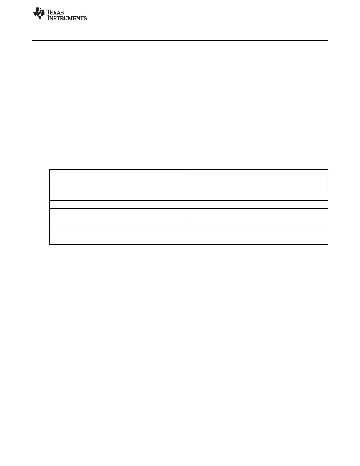
Table 25-1. Radio RAM Pages
Page Number Assignment
0 RAM-based registers
1 For Rx with auto ACK: ACK payload FIFO for addresses 2 and 3
2 For Rx with auto ACK: ACK payload FIFO for addresses 4 and 5
3 For Rx with auto ACK: ACK payload FIFO for addresses 6 and 7
4 Free for MCU use
5 Additional RAM-based registers/Reserved for LLE
6 Rx FIFO
Tx FIFO/for Rx with auto ACK: ACK payload FIFO for addresses
7
0 and 1
The active memory page is selected in register RFRAMCFG.PRE. The selected page is accessible at
XDATA addresses 0x6000–0x607F. The Rx FIFO page (page 6) is also accessible at XDATA addresses
0x6080–0x60FF. The Tx FIFO page (page 7) is also accessible at XDATA addresses 0x6100–0x617F.
A page is used for transferring parameters to the LLE, see Section 25.3.3.
There is no hardware protection to prevent the MCU from overwriting memory used by the LLE and the
FIFO. Thus the MCU should never write to page 5 (except for special dedicated registers). The MCU
should write to pages 0, 1, 2, 3, and 7 only as specified in this chapter. Writes to the FIFO pages should
only be done in ways compatible with FIFO operation, except for accessing the Tx FIFO page while
running an Rx task with auto ACK.
Pages 0, 1, 6, and 7 have retention in all power modes, whereas the contents of pages 2–5 are lost in
PM2 and PM3.
Radio core hardware registers are located at XDATA addresses 0x6180–0x61F7. Figure 25-1 shows the
mapping of radio memory to MCU XDATA memory space.
293
SWRU191C–April 2009–Revised January 2012 CC2541 Proprietary Mode Radio
Submit Documentation Feedback
Copyright © 2009–2012, Texas Instruments Incorporated

 Loading...


