USB Registers
www.ti.com
by setting USBPOW.RESUME to 1 for approximately 10 ms. According to the USB 2.0 Specification [3],
the resume signaling must be present for at least 1 ms and no more than 15 ms. It is, however,
recommended to keep the resume signaling for approximately 10 ms. Notice that support for remote
wakeup must be declared in the USB descriptor, and that the USB host must grant the device the privilege
to perform remote wakeup (through a SET_FEATURE request).
21.12 USB Registers
This section describes all USB registers used for control and status for the USB. The USB registers reside
in XDATA memory space in the region 0x6200–0x622B. These registers can be divided into three groups:
The common USB registers, the indexed endpoint registers, and the endpoint FIFO registers. The indexed
endpoint registers represent the currently selected endpoint. The USBINDEX register is used to select the
endpoint.
The registers return to their reset values and the FIFOs are cleared when the chip enters PM2 or PM3.
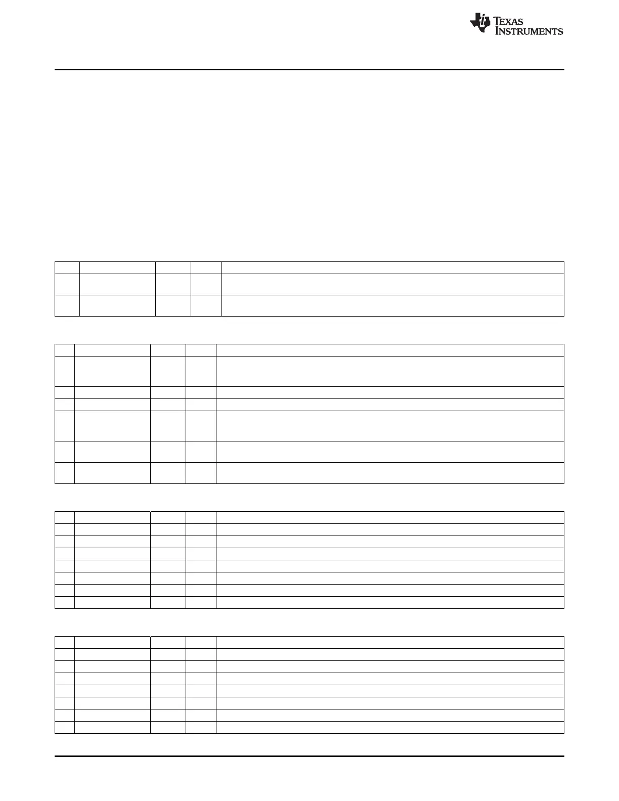
USBADDR (0x6200) – Function Address
Bit Name Reset R/W Description
7
UPDATE
0 R
This bit is set when the USBADDR register is written and cleared when the address becomes
effective.
6:0
USBADDR[6:0]
000 000 R/W Device address
0
USBPOW (0x6201) – Power/Control Register
Bit Name Reset R/W Description
7
ISO_WAIT_SOF
0 R/W When this bit is set to 1, the USB controller sends zero-length data packets from the time
INPKT_RDY is asserted and until the first SOF token has been received. This only applies to
isochronous endpoints.
6:4 – 000 R0 Reserved
3
RST
0 R During reset signaling, this bit is set to 1.
2
RESUME
0 R/W Drives resume signaling for remote wakeup. According to the USB Specification, the duration
of driving resume must be at least 1 ms and no more than 15 ms. It is recommended to keep
this bit set for approximately 10 ms.
1
SUSPEND
0 R
Suspend mode entered. This bit is only used when SUSPEND_EN = 1. Reading the USBCIF
register or asserting RESUME clears this bit.
0
SUSPEND_EN
0 R/W Suspend enable. When this bit is set to 1, suspend mode is entered when the USB has been
idle for 3 ms.
USBIIF (0x6202) – IN Endpoints and EP0 Interrupt Flags
Bit Name Reset R/W Description
7:6 – 00 R0 Reserved
5
INEP5IF
0 R, H0 Interrupt flag for IN endpoint 5. Cleared by hardware when read
4
INEP4IF
0 R, H0 Interrupt flag for IN endpoint 4. Cleared by hardware when read
3
INEP3IF
0 R, H0 Interrupt flag for IN endpoint 3. Cleared by hardware when read
2
INEP2IF
0 R, H0 Interrupt flag for IN endpoint 2. Cleared by hardware when read
1
INEP1IF
0 R, H0 Interrupt flag for IN endpoint 1. Cleared by hardware when read
0
EP0IF
0 R, H0 Interrupt flag for endpoint 0. Cleared by hardware when read
USBOIF (0x6204) – OUT-Endpoint Interrupt Flags
Bit Name Reset R/W Description
7:6 – – R0 Reserved
5
OUTEP5IF
0 R, H0 Interrupt flag for OUT endpoint 5. Cleared by hardware when read
4
OUTEP4IF
0 R, H0 Interrupt flag for OUT endpoint 4. Cleared by hardware when read
3
OUTEP3IF
0 R, H0 Interrupt flag for OUT endpoint 3. Cleared by hardware when read
2
OUTEP2IF
0 R, H0 Interrupt flag for OUT endpoint 2. Cleared by hardware when read
1
OUTEP1IF
0 R, H0 Interrupt flag for OUT endpoint 1. Cleared by hardware when read
0 – – R0 Reserved
200
USB Controller SWRU191C– April 2009– Revised January 2012
Submit Documentation Feedback
Copyright © 2009–2012, Texas Instruments Incorporated

 Loading...


