Preamble
SFD MHR FCSLEN
(1) (3)(2)
MAC Payload
Received Frame
M0110-01
0 0 0 0 0 0 0 0
7
A
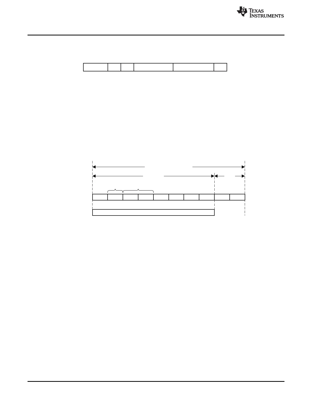
Preamble
Synchronization Header
SFD
IEEE 802.15.4
CC2530
1 Symbol 1 Byte
M0111-02
2 (PREAMBLE_LENGTH + 2) Zero Symbols
Transmit Mode
www.ti.com
23.8.7 Transmitted Frame Processing
The radio performs the following frame generation tasks for TX frames:
(1) Generation and automatic transmission of the PHY layer synchronization header, which consists of the
preamble and the SFD
(2) Transmission of the number of bytes specified by the frame-length field
(3) Calculation of and automatic transmission of the FCS (can be disabled)
Figure 23-7. Single Transmitted Frame
The recommended usage is to write the frame-length field followed by the MAC header and MAC payload
to the TXFIFO and let the radio handle the rest. Note that the frame-length field must include the two FCS
bytes, even though the radio adds these automatically.
23.8.8 Synchronization Header
Figure 23-8. Transmitted Synchronization Header
The radio has programmable preamble length. The default value is compliant with [1], and changing the
value makes the system noncompliant to IEEE 802.15.4.
The preamble sequence length is set by MDMCTRL0.PREAMBLE_LENGTH. Figure 23-8 shows how the
synchronization header relates to the IEEE 802.15.4 specification.
When the required number of preamble bytes has been transmitted, the radio automatically transmits the
1-byte SFD. The SFD is fixed, and it is not possible to change this value from software.
23.8.9 Frame-Length Field
When the SFD has been transmitted, the modulator starts to read data from the TXFIFO. It expects to find
the frame-length field followed by the MAC header and MAC payload. The frame-length field is used to
determine how many bytes are to be transmitted.
Note that the minimum frame length is 3 bytes when AUTOCRC = 1 and 1 byte when AUTOCRC = 0.
23.8.10 Frame Check Sequence
When the FRMCTRL0.AUTOCRC control bit is set, the FCS field is automatically generated and appended
to the transmitted frame at the position defined by the frame-length field. The FCS is not written to the
TXFIFO, but stored in a separate 16-bit register. It is recommended always to have AUTOCRC enabled,
except possibly for debug purposes. If FRMCTRL0.AUTOCRC = 0, then the modulator expects to find the
FCS in the TXFIFO, so software must generate the FCS and write it to the TXFIFO along with the rest of
the MPDU.
The hardware implementation of the FCS calculator is shown in Figure 23-9. See [1] for further details.
232
CC253x Radio SWRU191C–April 2009–Revised January 2012
Submit Documentation Feedback
Copyright © 2009–2012, Texas Instruments Incorporated

 Loading...


