Bit-Stream Processor
www.ti.com
25.3.4 Variables in RAM Page 5
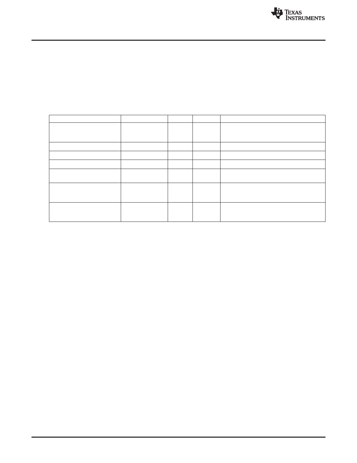
Some additional RAM registers are placed in page 5 of the RFCORE RAM. These variables have the
prefix PRFX and are listed in Table 25-7. The addresses overlap other RAM registers, and to access them
page 5 must be selected using the RFRAMCFG register; see Section 25.3. Some of the registers have a
reset value. This value is written by the LLE shortly after it has been taken out of reset by
LLECTRL.LLE_EN being set to 1. If the MCU must modify these registers, the modification must be done
each time the LLE is reset. After taking the LLE out of reset, the MCU may modify the registers after
LLASTAT.LLE_IDLE has gone high.
Table 25-7. RAM-Based Registers in RAM Page 5
(1)
Name Addr Prot Reset Val Description
Last frequency offset estimate, read from the
0x6006 Sem1/R –
PRFX_LAST_FREQEST FREQEST register at the end of receiving each
packet
0x6008 Sem1 0x20 Lower RSSI limit for use in AGC algorithm
PRFX_RSSI_LIM_LOWER
0x6009 Sem1 0x3C Upper RSSI limit for use in AGC algorithm
PRFX_RSSI_LIM_UPPER
0x600A Sem1 0x14 Difference between high and low RSSI gain
PRFX_RSSI_DIFF
LNAGAIN setting to use while close to
0x600B Sem1 0x4A
PRFX_LNAGAIN_SAT
saturation
Duration of tone in start of packet if
0x600C–0x600D Sem1 0x064A
PRFX_TONE_DURATION PRF_PKT_CONF.START_TONE = 1,
given in 31.25-ns units
Time to subtract from Tx synthesizer calibration
0x600E–0x600F Sem0 0x0600
PRFX_TONE_OFFSET time if PRF_PKT_CONF.START_TONE =
1, given in 31.25-ns units
(1)
Note that the LLE is reset when the device enters PM2 or PM3. This means that the PRFX registers must be re-initialized after
coming up from one of these power modes.
The parts of RAM page 5 that are not listed in Table 25-7 are reserved for use by the LLE and should not
be written by the MCU.
25.4 Bit-Stream Processor
The bit-stream processor (BSP) supports automatic insertion of CRC and detection of CRC error with a
programmable polynomial of 8, 16, 24, or 32 bits.
The bit-stream processor also supports whitening and de-whitening. The whitening sequences
supported are a PN7 sequence and a PN 9 sequence compatible with CC2500/CC2510.
The bit-stream processor is used by the LLE to do the whitening and CRC generation and checking. This
operation is based on the configuration set up by the MCU. The BSP can also be run in a coprocessor
mode to calculate whitened sequences and CRCs. This must only be done while the LLE is not running.
25.4.1 Whitening
The BSP supports two whiteners, a PN7 and a PN9 whitener. The register BSP_MODE is used to enable or
disable each whitener. When no whitener is enabled, it outputs zero. The whitener sequence is XORed
with the transmitted or received signal.
It is possible to enable both whiteners. This is useful, e.g., in conjunction with the test command
CMD_TX_TEST (Section 25.9.3) to transmit a white test signal.
25.4.1.1 PN7 Whitening
The PN7 whitener is shown in Figure 25-3. It has a 7-bit whitening shift register w used for calculating the
PN sequence given by the polynomial x
7
+ x
4
+ 1. The output is the same as the shift register feedback.
304
CC2541 Proprietary Mode Radio SWRU191C– April 2009–Revised January 2012
Submit Documentation Feedback
Copyright © 2009–2012, Texas Instruments Incorporated

 Loading...


