BSP_MODE.W_PN7_EN
B0466-01
Output
x
0
x
4
x
7
w
0
w
1
w
3
w
2
w
4
w
5
w
6
PN7 Whitening
www.ti.com
Bit-Stream Processor
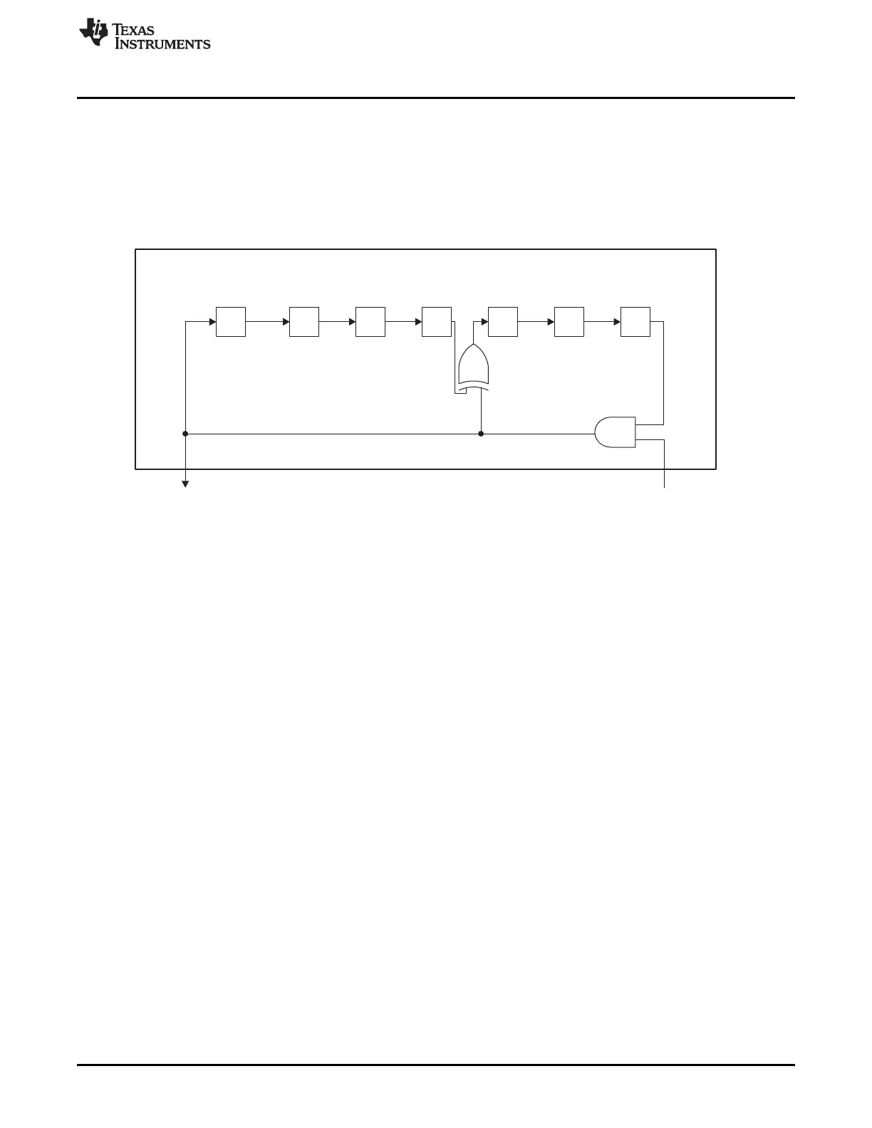
The w register must be initialized by writing w into register BSP_W.W before starting receiving or
transmitting a packet. Doing this sets w
6
to BSP_W[0], w
5
to BSP_W[1] and so on up to w
1
to
BSP_W[5]; w
0
is set to 1.
When running normal receive or transmit tasks, writing to BSP_W is done by the LLE, which writes the
value in PRF_W_INIT to this register, but for test commands and co-processor mode, the BSP_W register
must be written by the MCU.
The PN7 whitener is enabled by the bit W_PN7_EN of the BSP_MODE register.
Figure 25-3. PN7 Whitening
25.4.2 CC2500-Compatible PN9 Whitening
The CC2500-compatible PN9 whitener is shown in Figure 25-4. It has a 9-bit whitening shift register s and
an 8-bit output register b. It produces a whitening sequence compatible with CC2500, CC2510 and other
TI devices. These devices use the polynomial x
9
+ x
4
+ 1. The whitening sequence is produced one byte
at a time, and the byte is bit-reversed before being XORed with a received or transmitted byte. Before
starting reception or transmission of a packet, the s and b registers must be initialized to all ones by
writing a 1 to register BSP_W.W_PN9_RESET. As for the PN7 whitener, this is done by the LLE for normal
receive and transmit tasks, provided that bit 7 of PRF_W_INIT is 1.
In Figure 25-4, the dashed arrows going from the s blocks to the b blocks denote a copy that takes place
after the whitening of one byte is done. This means that the first byte is whitened by the 8 bits that are in
the b register after initialization (all ones). As this byte is being whitened, the s register is updated. After
the first byte is whitened, the value of the s register is copied into the b register and used for whitening the
second byte.
The CC2500-compatible whitener is enabled by bit W_PN9_EN of the BSP_MODE register.
305
SWRU191C–April 2009–Revised January 2012 CC2541 Proprietary Mode Radio
Submit Documentation Feedback
Copyright © 2009–2012, Texas Instruments Incorporated

 Loading...


