RESET
WATCHDOG
TIMER
IRQ CTRL
FLASH CTRL
DEBUG
INTERFACE
CLOCK MUX
and
CALIBRATION
DMA
8051 CPU
CORE
32-MHz
CRYSTAL OSC
OP-AMP
32.768-kHz
CRYSTAL OSC
HIGH-
SPEED
RC-OSC
POWER MANAGEMENT CONTROLLER
USART 0
USB
USART 1
TIMER 1 (16-Bit)
TIMER 3 (8-Bit)
TIMER 4 (8-Bit)
TIMER 2
(BLE LL TIMER)
FLASH
FIFOCTRL
1 KB SRAM
ON-CHIP VOLTAGE
REGULATOR
POWER-ON RESET
BROWN OUT
VDD (2 V–3.6 V)
DCOUPL
RESET_N
XOSC_Q2
XOSC_Q1
P2_4
P1_7
P0_7
P2_3
P1_6
P0_6
P2_2
P1_5
P0_5
P1_2
P0_2
P2_1
P1_4
P0_4
P1_1
P0_1
P2_0
P1_3
P0_3
P1_0
P0_0
MODULATOR
DEMODULATOR
RECEIVE
TRANSMIT
FREQUENCY
SYNTHESIZER
SYNTH
RF_P
RF_N
B0301-05
RADIO REGISTERS
SFR Bus
SFR Bus
DS
ADC
AUDIO/DC
AES
ENCRYPTION
AND
DECRYPTION
MEMORY
ARBITRATOR
FLASH
UNIFIED
SFR
IRAM
XRAM
PDATA
SLEEP TIMER
32-kHz
RC-OSC
I/O CONTROLLER
DIGITAL
ANALOG
MIXED
ANALOG COMPARATOR
USB_N
USB_P
Radio Arbiter
Link Layer Engine
www.ti.com
Overview
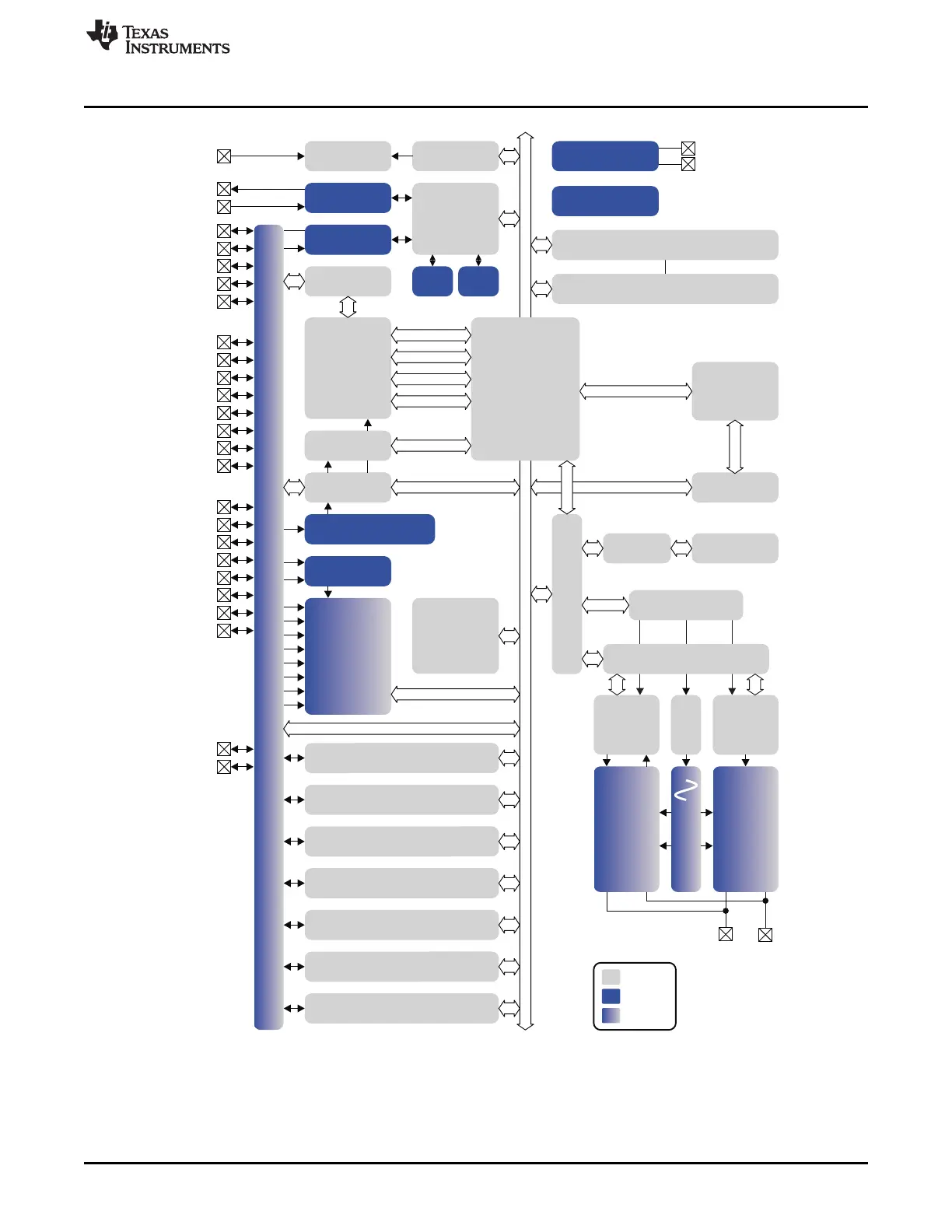
Figure 1-2. CC2540 Block Diagram
The modules can be roughly divided into one of three categories: CPU and memory related modules;
modules related to peripherals, clocks, and power management; and radio-related modules.
21
SWRU191C–April 2009–Revised January 2012 Introduction
Submit Documentation Feedback
Copyright © 2009–2012, Texas Instruments Incorporated

 Loading...


