Timer 1 Registers
www.ti.com
There are no triggers associated with channels 3 and 4.
9.12 Timer 1 Registers
This section describes the Timer 1 registers, which consist of the following registers:
• T1CNTH – Timer 1 count high
• T1CNTL – Timer 1 count low
• T1CTL – Timer 1 control
• T1STAT – Timer 1 status
• T1CCTLn – Timer 1 channel n capture/compare control
• T1CCnH – Timer 1 channel n capture/compare value high
• T1CCnL – Timer 1 channel n capture/compare value low
The TIMIF.OVFIM register bit resides in the TIMIF register, which is described together with the Timer 3
and Timer 4 registers.
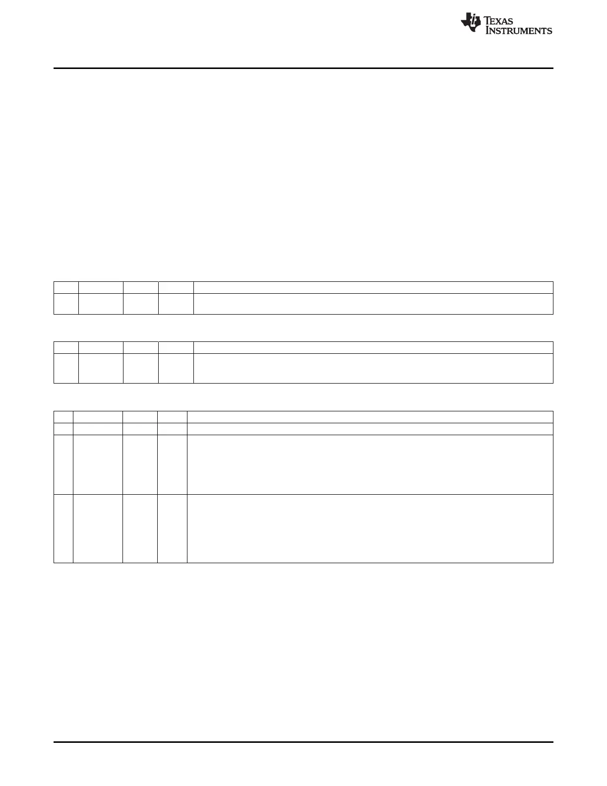
T1CNTH (0xE3) – Timer 1 Counter High
Bit Name Reset R/W Description
7:0
CNT[15:8
0x00 R Timer count high-order byte. Contains the high byte of the 16-bit timer counter buffered at the time
]
T1CNTL is read
T1CNTL (0xE2) – Timer 1 Counter Low
Bit Name Reset R/W Description
7:0
CNT[7:0]
0x00 R/W Timer count low-order byte. Contains the low byte of the 16-bit timer counter. Writing anything to
this register results in the counter being cleared to 0x0000 and initializes all output pins of
associated channels.
T1CTL (0xE4) – Timer 1 Control
Bit Name Reset R/W Description
7:4 – 0000 R0 Reserved
3:2
DIV[1:0]
00 R/W Prescaler divider value. Generates the active clock edge used to update the counter as follows:
00: Tick frequency/1
01: Tick frequency/8
10: Tick frequency/32
11: Tick frequency/128
1:0
MODE
00 R/W Timer 1 mode select. The timer operating mode is selected as follows:
[1:0]
00: Operation is suspended.
01: Free-running, repeatedly count from 0x0000 to 0xFFFF.
10:
Modulo, repeatedly count from 0x0000 to T1CC0.
11:
Up/down, repeatedly count from 0x0000 to T1CC0 and from T1CC0 down to 0x0000.
118
Timer 1 (16-Bit Timer) SWRU191C–April 2009–Revised January 2012
Submit Documentation Feedback
Copyright © 2009–2012, Texas Instruments Incorporated

 Loading...


