www.ti.com
Timer 3 and Timer 4 Registers
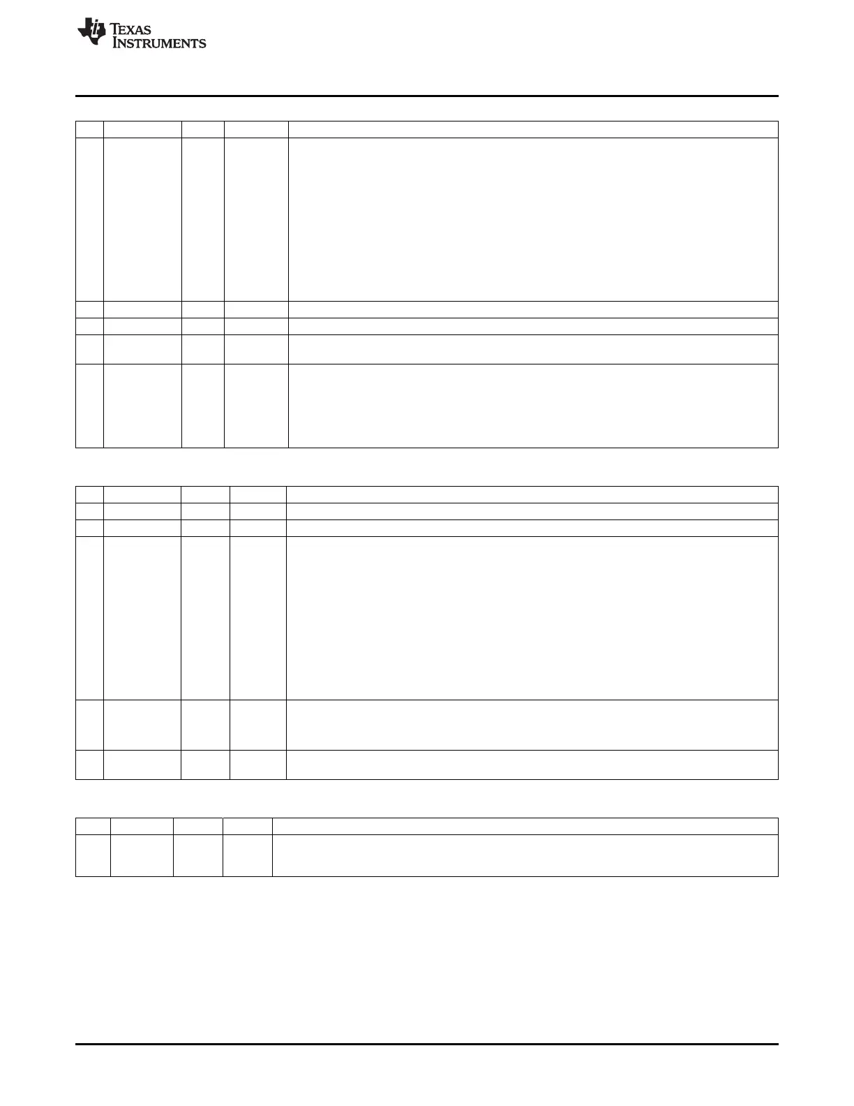
T4CTL (0xEB) – Timer 4 Control
Bit Name Reset R/W Description
7:5
DIV[2:0]
000 R/W Prescaler divider value. Generates the active clock edge used to clock the timer from
CLKCONCMD.TICKSPD as follows:
000: Tick frequency/1
001: Tick frequency/2
010: Tick frequency/4
011: Tick frequency/8
100: Tick frequency/16
101: Tick frequency/32
110: Tick frequency/64
111: Tick frequency/128
4
START
R/W Start timer. Normal operation when set, suspended when cleared
3
OVFIM
1 R/W Overflow interrupt mask
2
CLR
0 R0/W1 Clear counter. Writing a 1 to CLR resets the counter to 0x00 and initialize all output pins of
associated channels. Always read as 0.
1:0
MODE[1:0]
0 R/W Timer 4 mode. Select the mode as follows:
00: Free running, repeatedly count from 0x00 to 0xFF
01: Down, count from T4CC0 to 0x00
10: Modulo, repeatedly count from 0x00 to T4CC0
11: Up/down, repeatedly count from 0x00 to T4CC0 and down to 0x00
T4CCTL0 (0xEC) – Timer 4 Channel 0 Capture/Compare Control
Bit Name Reset R/W Description
7 – 0 R0 Reserved
6
IM
1 R/W Channel 0 interrupt mask
5:3
CMP[2:0]
000 R/W Channel 0 compare output-mode select. Specified action occurs on output when timer value
equals compare value in T4CC0.
000: Set output on compare
001: Clear output on compare
010: Toggle output on compare
011: Set output on compare-up, clear on 0
100: Clear output on compare-up, set on 0
101: Set output on compare, clear on 0xFF
110: Clear output on compare, set on 0x00
111: Initialize output pin. CMP[2:0] is not changed
2
MODE
0 R/W Mode. Select Timer 4 channel 0 mode
0: Capture mode
1: Compare mode
1:0
CAP[1:0]
00 R/W Capture mode select. 00 – No capture, 01 – Capture on rising edge, 10 – Capture on falling
edge, 11 – Capture on both edges
T4CC0 (0xED) – Timer 4 Channel 0 Capture/Compare Value
Bit Name Reset R/W Description
7:0
VAL[7:0]
0x00 R/W Timer 4 capture/compare value, channel 0. Writing to this register when T4CCTL0.MODE = 1
(compare mode) causes the T4CC0.VAL[7:0] update to the written value to be delayed until
T4CNT.CNT[7:0] = 0x00.
131
SWRU191C–April 2009–Revised January 2012 Timer 3 and Timer 4 (8-Bit Timers)
Submit Documentation Feedback
Copyright © 2009–2012, Texas Instruments Incorporated

 Loading...


