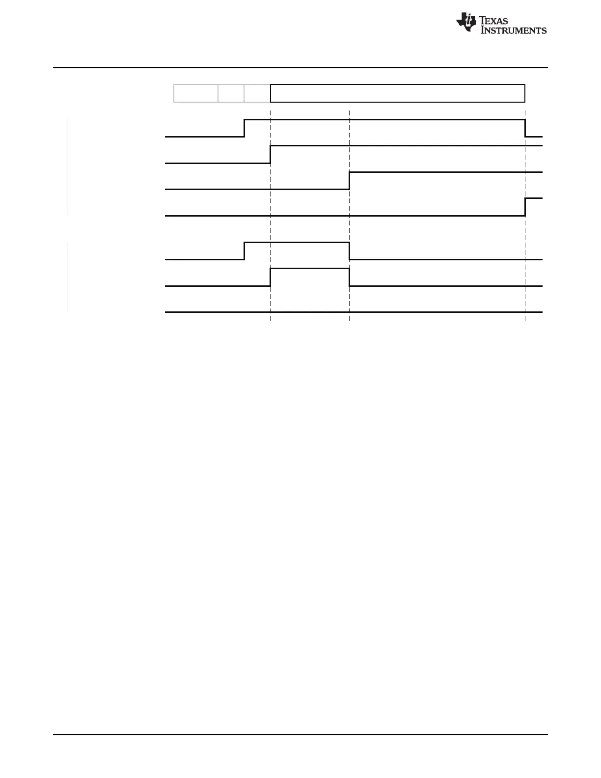
FSMSTAT1:SFD
Received Frame
Preamble
SFD LEN
FSMSTAT1:FIFO
FSMSTAT1:FIFOP
(Low Threshold)
FSMSTAT1:FIFOP
(High Threshold)
Accepted Frame
Rejected Frame
FSMSTAT1:SFD
FSMSTAT1:FIFO
FSMSTAT1:FIFOP
MPDU(LEN[6:0]Bytes)
FirstByte
Received
Frame
Filtering
Complete
Last Byte
Received
T0322-01
RXFIFO Access
www.ti.com
Figure 23-19. Behavior of FIFO and FIFOP Signals
When using the FIFOP as an interrupt source for the microcontroller, the FIFOP threshold should be
adjusted by the interrupt service routine to prepare for the next interrupt. When preparing for the last
interrupt for a frame, the threshold should match the number of bytes remaining.
23.10.2 Error Conditions
There are two error conditions associated with the RXFIFO:
• Overflow, in which case the RXFIFO is full when another byte is received
• Underflow, in which case software attempts to read a byte from an empty RXFIFO
RX overflow is indicated by the RFERRF.RXOVERF flag being set and by the signal values
FSMSTAT1.FIFO = 0 and FSMSTAT1.FIFOP = 1. When the error occurs, frame reception is halted. The
frames currently stored in the RXFIFO may be read out before the condition is cleared with the
ISFLUSHRX strobe. Note that rejected frames can generate RX overflow if the condition occurs before the
frame is rejected.
RX underflow is indicated by the RFERRF.RXUNDERF flag being set. RX underflow is a serious error
condition that should not occur in error-free software, and the RXUNDERF event should only be used for
debugging or in a watchdog function. Note that the RXUNDERF error is not generated when the read
operation occurs simultaneously with the reception of a new byte.
23.10.3 RSSI
The radio has a built-in received signal-strength indication (RSSI), which calculates an 8-bit signed digital
value that can be read from a register or automatically appended to received frames. The RSSI value is
the result of averaging the received power over eight symbol periods (128 μs) as specified by IEEE
802.15.4 [1].
The RSSI value is a 2s-complement signed number on a logarithmic scale with 1-dB steps.
244
CC253x Radio SWRU191C–April 2009–Revised January 2012
Submit Documentation Feedback
Copyright © 2009–2012, Texas Instruments Incorporated

 Loading...


