WWC T1 Set Up & Maintenance Manual Product Information
Document Ref 905675-001 Rev 2 Page 2-3
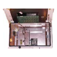
ARCHITECTURAL OVERVIEW
Fig. 1 Calculator Block Diagram
2.2.1 EXTERNAL POWER SUPPLY
The external power supply contains the following components:-
•A power distribution unit High Voltage Unit (HVU) including transformer
•A rechargeable back-up battery
2.2.2 MAINBOARD
The mainboard (version 3++) includes the calculator module and the Hydraulic
Controller Module (HCM):-
•The calculator module is able to manage two deliveries independently (one on
each road side); control the deliveries; maintain the volume and amount counters;
control the transaction displays and hydraulic units; and communicate with the
self-service device.
•The HCM is responsible for supporting the hydraulic interface by checking the
volume pulser devices; counting and checking the two incoming line volume
pulses; controlling the motor and valves and updating the electro-mechanical
totalisers.
The mainboard provides all the interfaces required to drive the ‘low-end’ hydraulics
without the need for an I/O board - single product and twin functionality (two
motors, two pulsers, four valves).
Issue A
COM
Calculator Module
HCM
HVU
Mains
UAM/
UAK
OCB
Battery
VRC
Low End H
draulic
(Single/Twin)
UAK
Displa
s
Valves, motors and sensors
Mainboard MB251
I/O Board
H1 H2 H3
H4
H
draulic Units
(pulsers, valves, motors)
Dipnet
IEB
Communication
Interfaces
Nozzle Bus
Interface
OPB
CSD-L
CSD-F
Dispenser I/O
O
tional Peri
herals:
UPD
Product Indication
Others
IRM
1
2
3
5
4
HOM
Hydraulic Option Modules
I/O extensions
Dispenser li
ht,
Electr totaliser
CSD-L
CSD-F
OPU
ODU
 Loading...