Note:Ifelectricalproblemsexistwithasolenoidvalvecoil,afaultmayhave
occurredthatwouldbeindicatedbyafaultcodeontheInfoCenterdisplay.
Beforeconsideringthatsolenoidvalvecoilserviceworkisnecessary,check
foranyexistingfaultcodes.
TestingtheHydraulicSolenoidValveCoils
Note:Beforeyoudisconnectthesolenoidvalvecoils,testthesolenoidsand
theircircuitwiringasTECoutputswiththeInfoCenterdisplay;refertoUsingthe
InfoCenterDisplayforTroubleshooting(page7–28).IftheInfoCenterveries
thatthesolenoidcoilsandcircuitwiringarefunctioningcorrectly,thennomore
testingisnecessary.
1.Parkthemachineonalevelsurface,lowerthecuttingunits,shutoffthe
engine,settheparkingbrake,andremovethekeyfromthekeyswitch.
g214066
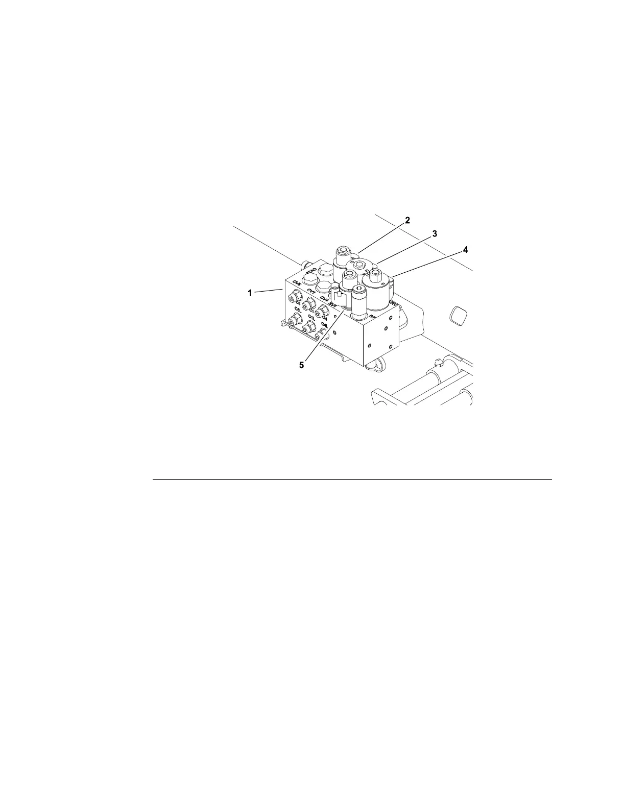
Figure265
1.Liftcontrolmanifold4.SVRVsolenoid
2.SV3solenoid5.SV1solenoid
3.SV2solenoid
2.Togetaccesstothemowcontrolmanifold,raiseandsupporttheoperator
seat(Figure264).Togetaccesstotheliftcontrolmanifold,removethe
operatoroorplate(Figure265).
3.Identifythecoilbymeasuringtheheightanddiameterofthecoil.
4.Disconnectthewireharnessconnectorfromthehydraulicsolenoidvalve
coilthatistobetested.
Note:Beforetakingthesmallresistancereadingswithadigitalmultimeter,
shortthemultimetertestleadstogether.Themultimeterdisplaysasmall
resistancevalue(usually0.5ohmsorless).Thisresistanceisbecauseofthe
internalresistanceofthemultimeterandtestleads.Subtractthisvaluefrom
themeasuredvalueofthecomponentthatyouaretesting.
Note:Thesolenoidcoilresistanceshouldbemeasuredwithsolenoidat
approximately20°C(68°F).Resistancemaybeslightlydifferentthanlisted
atdifferenttemperatures.Typically,adamagedsolenoidcoilwilleitherbe
shorted(verylowornoresistance)oropen(inniteresistance).
5.Useamultimeter(ohmssetting),measuretheresistancebetweenthe2
connectorterminalsonthesolenoidcoil.Theresistanceforthesolenoidcoils
isidentiedintheSolenoidValveCoilSpecicationsT able(page7–97).
ElectricalSystem:TestingtheElectricalComponents
Page7–96
Reelmaster
®
5410/5510/5610Series
15216SLRevC
 Loading...

