InstallingtheBacklapSwitches
g214065
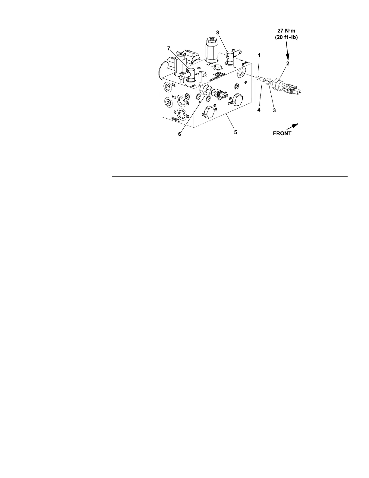
Figure287
1.Ball
3.O-ring5.Mowcontrolmanifold
2.Frontbacklapswitch4.Dowelpin6.Rearbacklapswitch
1.Ensurethatthedowelpinandballareplacedinthemanifoldportasshown
inFigure287.
2.InstallthebacklapswitchwithnewO-ringintothemanifoldportandtorque
theswitchto27N∙m(20ft-lb).
3.Connecttheharnesselectricalconnectortothebacklapswitch.Usethe
InfoCenterdisplay(refertoDiagnosticsScreen(page7–19)(Backlapitem))
toverifythatthebacklapswitchesarefunctioningcorrectly.
4.Lowertheoperatorseat.
Reelmaster
®
5410/5510/5610Series
Page7–123
ElectricalSystem:ServiceandRepairs
15216SLRevC
 Loading...

