Groundsmaster 4100--D/4110--DHydraulic System Page 4 -- 104
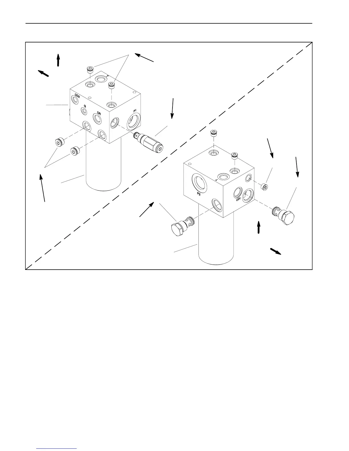
Filter Manifold Service
1. Filter manifold
2. Check valve (reservoir return)
3. Oil filter element
4. Check valve (filter bypass)
5. #6 zero leak plug with O--ring
6. Charge relief valve
7. #8 zero leak plug with O--ring
Figure 71
FRONT
UP
6
7
1
5
5
4
2
FRONT
UP
3
3
30 ft--lb
(41 N--m)
50 ft--lb
(67 N--m)
25 ft--lb
(34 N--m)
25 ft--lb
(34 N--m)
30 ft--lb
(41 N--m)
25 ft--lb
(34 N--m)
NOTE: The ports on the manifold are marked for easy
identification of components. Example: P2 is the gear
pumpconnectionportandTistheconnectionforthehy-
draulicreservoirreturnport(seeHydraulicSchematicin
Chapter 10 -- Foldout Drawings to identify the function
ofthe hydraulic lines and cartridge valvesateach port).
NOTE: Thefiltermanifoldusesseveralzeroleakplugs.
Theseplugs haveataperedsealing surfaceontheplug
head that is designed to resist vibration induced plug
loosening. The zero leak plugs also have an O--ring as
asecondaryseal.Ifzeroleakplugremovalisnecessary,
lightlyrap theplughead usingapunch andhammerbe-
fore using an allen wrench to remove the plug: the im-
pactwillallowplugremovalwithlesschanceofdamage
to the socket head of the plug.
 Loading...


