Groundsmaster 4100--D/4110--D Hydraulic SystemPage 4 -- 25
Engine Cooling Fan Circuit
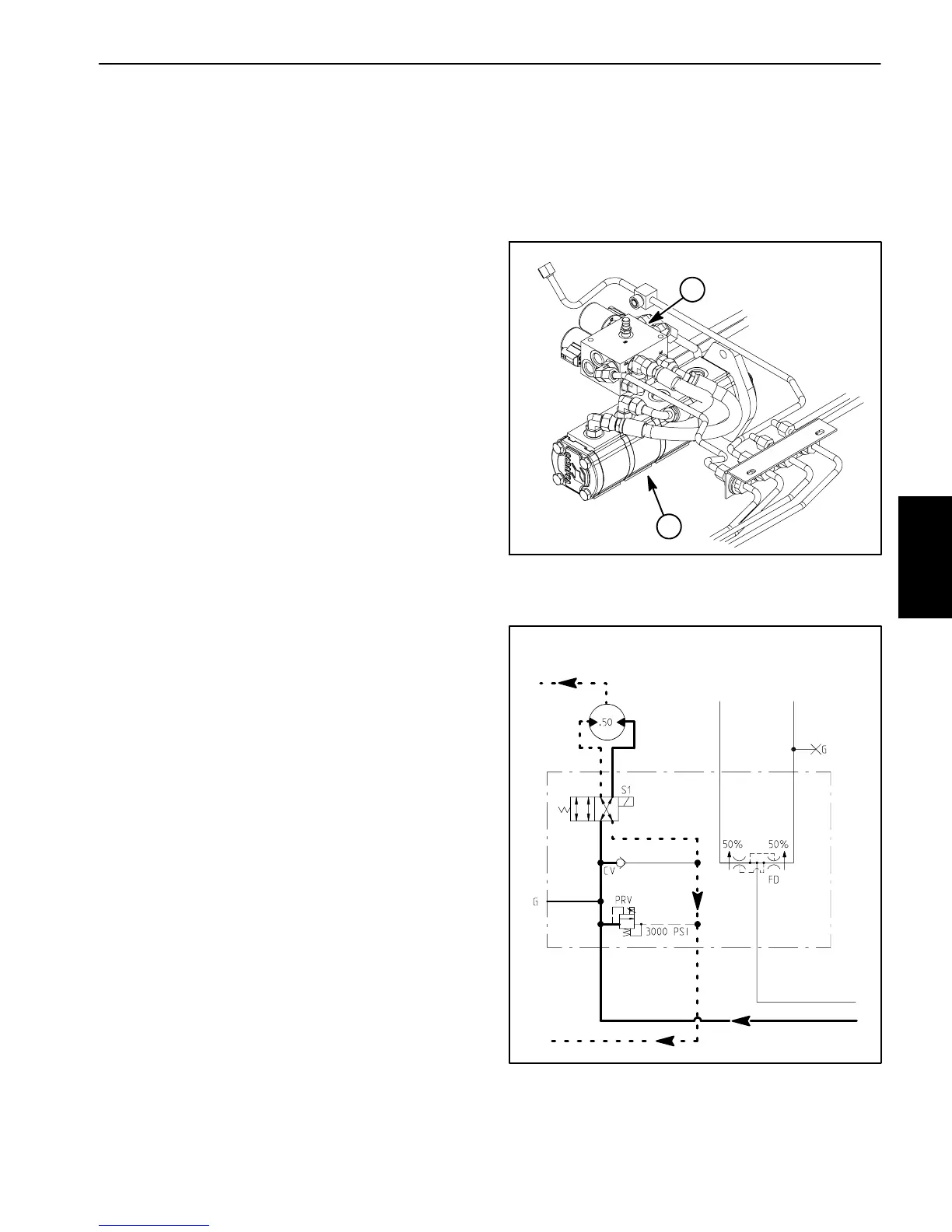
A four section gear pump is coupled to the piston (trac-
tion)pump.Thegearpumpsectionfarthestfromthepis-
ton pump supplies hydraulic flow for the engine cooling
fan circuit (Fig. 15).
The fan drive manifold controls the operation of the hy-
draulic motor that drives the engine cooling fan in addi-
tion to including the flow divider for the steering and lift
circuits. The electronically controlled proportional relief
valve(PRV)inthemanifoldcontrolstheoilflowtothefan
motor.Thefandrivemanifoldcontrols thespeedanddi-
rection of the fan motor based on electrical output from
the TEC--5002 controller.
Oil flow from the gear pump to the cooling fan motor is
controlled by the proportional relief valve (PRV) in the
fan drive manifold. This v alve adjusts fan circuit pres-
sure and flow based on a PWM (Pulse Width Modula-
tion)signalfromtheTEC--5002controller.Thecontroller
uses engine coolant and hydraulic oil temperatures as
inputstodeterminetheproperPWMsignalforthe(PRV)
valve. The fan circuit flow determines the speed of the
coolingfanmotorandthus,thespeedofthecoolingfan.
If the fan motor is stalled for any reason, the manifold
proportionalreliefvalve(PRV)hasas econdaryfunction
as a circuit relief to limit fan motor pressure to 3000 PSI
(207 bar).
When the engine is shut off, the over--running inertia
load of the fan blades keeps driving the fan motor and
turnsitintoapump.Thecheckvalve(CV)inthefandrive
manifold will open to keep the motor circuit full of oil so
the fan motor will not cavitate.
Forward Direction Fan Operation
Oilflowfromthegearpumpiss entthroughthede--ener-
gizedfanmanifoldsolenoidvalve(S1)torotatethecool-
ing fan motor. Return flow from the motor re-- enters the
manifold (port M2), through the de--energized solenoid
valve(S1),outofthemanifold(portT)andthenisrouted
through the oil cooler and oil filter.
Reverse Direction Fan Operation (Fig. 16)
TheTEC--5002controller canreversethe coolingfan to
clean debris from the rear intake screen. If hydraulic oil
and/or engine coolant temperatures increase to an un-
suitable level, a high PWM signal is sent to the (PRV)
valve to slow the cooling fan and direct pump oil flow to
the r eservoir. The controller then energizes solenoid
valve(S1)inthefandrivemanifoldtoreversecoolingfan
motoroilflowsothatthemotorrunsinthereversedirec-
tion.Alower PWMsignalissenttothePRVvalveallow-
ing oil flow to return to the fan motor but in the reverse
direction causing the motor and cooling fan to run in re-
verse. The controller determines the length of time that
thefanshouldberuninreversebeforefanrotationisre-
turned to the forward direction.
1. Gear pump 2. Fan drive manifold
Figure 15
1
2
Figure 16
FAN DRIVE
MANIFOLD
M1 M2 L
P1 P2T
FROM GEAR PUMP
TO OIL COOLER
TO RESERVOIR
TO LIFT/LOWER
CIRCUIT
TO STEERING
CIRCUIT
REVERSE DIRECTION SHOWN
(ENERGIZED)
Hydraulic
System
 Loading...


