Groundsmaster 4100--D/4110--D Page 5 -- 21 Electrical System
Fuses
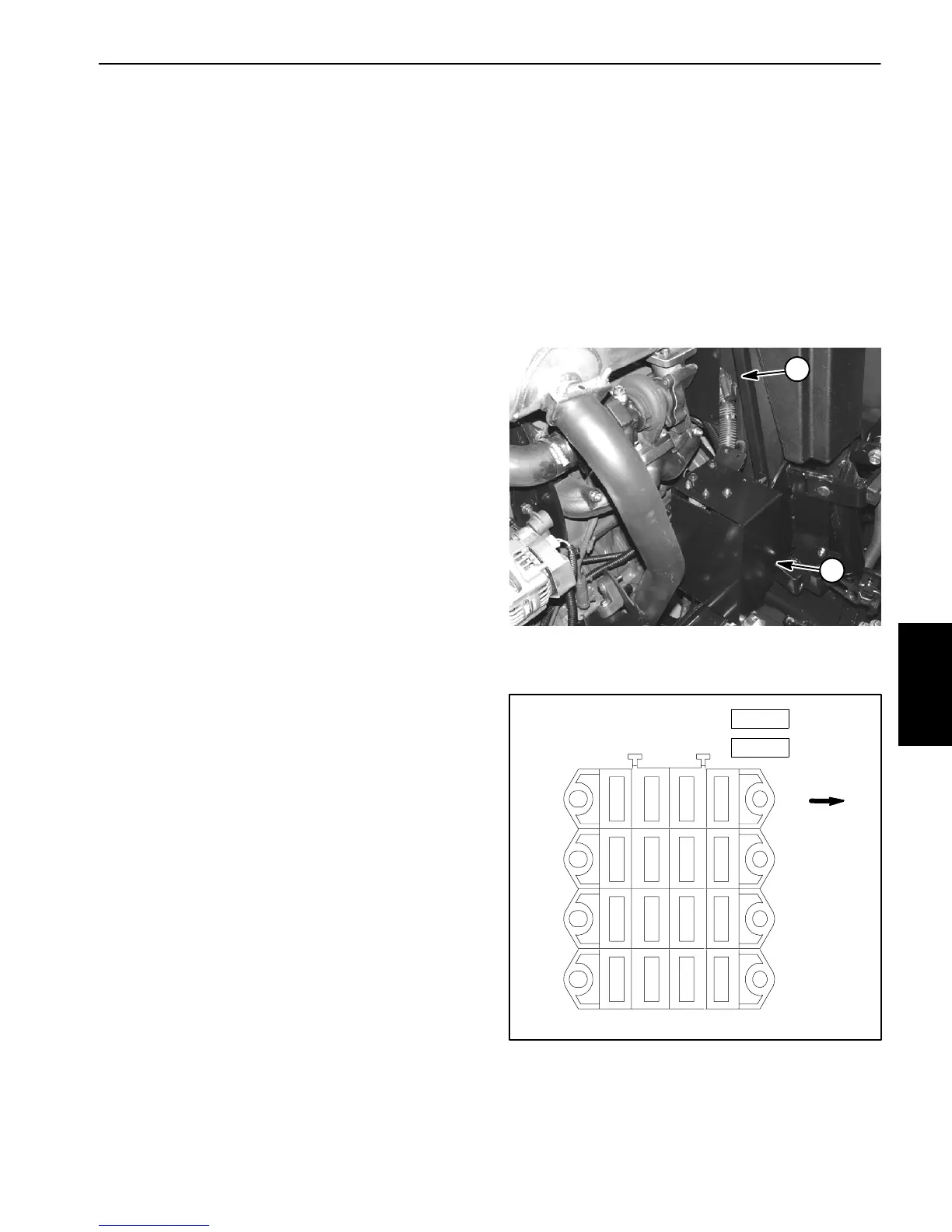
The fuse blocks are located in the power center under
the hood on the right side of the machine (Fig. 17).
Inadditiontothefuses inthe fuseblocks, a40 ampfuse
(F5--1) is included in the wire harness toprotect the pull
coilcircuit fortheengine run solenoid.This fuse resides
in a fuse holder near the starter motor (Fig. 17).
Fuse Identification and Function
UseFigure18toidentifyeachindividualfuseanditscor-
rect amperage. The fuses have the following functions.
FuseF1--1(20amp)protects engine starter circuit.
Fuse F1--3 (10 amp) protects light circuit on Ground-
smaster 4110--D.
FuseF1--4(10amp)protects signal light circuit on
Groundsmaster 4110-- D.
FuseF2--2(10amp)protects operator seat circuit.
FuseF2--3(10amp)protects power point circuit.
FuseF2--4(10amp)protectsmainpowersupplycircuit.
Fuse F3--1 (2 amp) protects logic power circuit to the
TEC--5002 controller.
Fuse F3--2 (7.5 amp) protects power supply for the
TEC--5002 controller outputs.
Fuse F3--3 (7.5 amp) protects power supply for the
TEC--5002 controller outputs.
Fuse F3--4 (7.5 amp) protects power supply for the
TEC--5002 controller outputs.
Fuse F4--1 (2 amp) protects logic power circuit to the
TEC--5001 controller.
Fuse F4--2 (7.5 amp) protects power supply for the
TEC--5001 controller outputs.
Fuse F4--3 (7.5 amp) protects power supply for the
TEC--5001 controller outputs.
Fuse F4--4 (7.5 amp) protects power supply for the
TEC--5001 controller outputs.
FuseM1(60A)protects engine glow plug circuit.
FuseM2(60A)protectsoperatorcabcircuitonGround-
smaster 4110--D.
Fuse Testing
Turn ignition switch to the ON position (do not start en-
gine). With the fuse installed in the fuse block, use a
multimetertoverifythat12VDCexistsatboth oftheter-
minal test points on the fuse. If 12 VDC exists at one of
thefusetestpointsbutnotattheother,thefuseisfaulty.
If necessary, make sure that ignition switch is OFF and
key is removed from switch. R emove fuse from fuse
blockandcheckthatfusehascontinuityacrossthefuse
terminals.
Figure 17
1. Power center 2. Fuse F5--1
1
2
Figure 18
F1
F2
1234
F3
F4
FRONT
2A
7.5 A
7.5A
7.5A
2A
7.5A
7.5A
7.5A
10A
10A
10A
20A
OPTION
M1 (60A)
M2 (60A)
10A
10A
OPTION
Electrical
System
 Loading...


