Groundsmaster 4100--D/4110--D Page 5 -- 37 Electrical System
Fuel Gauge
The fuel gauge can be tested using a new gauge as a
substitute or with the use of a DC voltage source and a
variableresistancebox (see Fuel Sender Testinginthis
section for additional information).
Testing
1. Make sure ignition switch is OFF. Remove key from
ignition switch.
2. Locate fuel gauge for testing (see Steering Tower
Disassembly in the Service and Repairs section of
Chapter 7 -- Chassis).
CAUTION
Make sure the voltage source is turned OFF be-
foreconnectingittotheelectricalcircuittoavoid
electrical shock and to prevent damaging the
gauge.
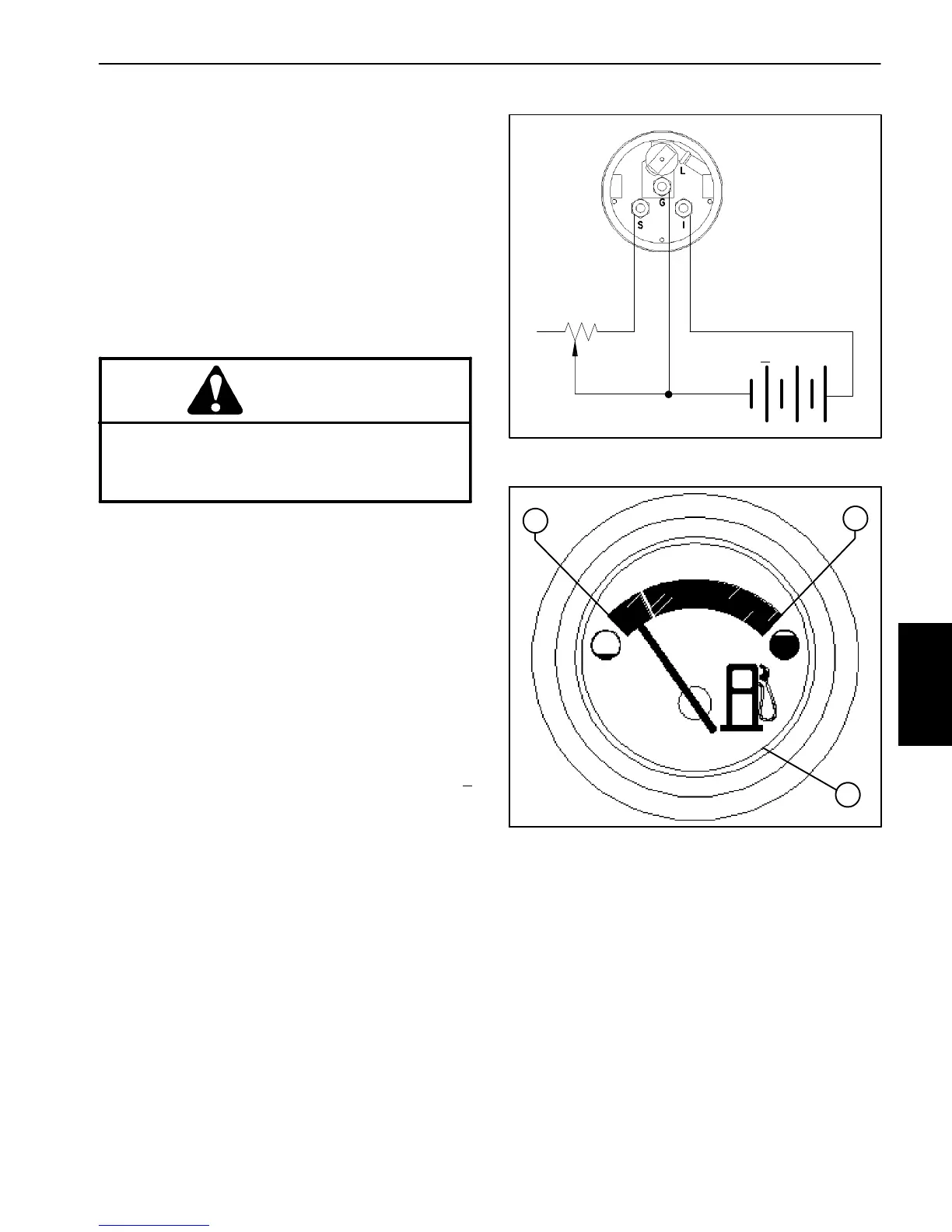
3. Connect fuel gauge to the variable resistance and
DC voltage source (Fig. 46).
NOTE: When reading the gauge test point, there are
two white dots on the gauge face below the edge of the
glasscoverforeach test point. For each variable resist-
ance setting, the needle must be pointed between the
two white dots.
4. Take test point readings (Fig. 47).
IMPORTANT: Allow circuit to warm up for at least 5
minutes before taking test readings.
A. Setvariableresistanceto240ohms.Applya14+
0.01 VDC to the circuit. The needle should point to
the left edge of the red area (empty).
B. Set variable resistance to 33 ohms. The needle
shouldpoint totheright edgeofthe green area(full).
5. Turn off the voltage source. Disconnect voltage
source, gauge and variable resistance.
6. Secure all removed components to steering tower
(see Steering Tower Assembly in the Service and Re-
pairs section of Chapter 7 -- Chassis).
Figure 46
+
--
VARIABLE
RESISTANCE
14 VDC + 0.01 VDC
1. Empty position
2. Full position
3. Glass face edge
Figure 47
1
2
3
Electrical
System
 Loading...


