Groundsmaster 4100--D/4110--DPage 5 -- 6Electrical System
Troubleshooting
CAUTION
Remove all jewelry, especially rings and
watches, before doing any electrical trouble-
shooting or testing. Disconnect the battery
cables unless the test requires battery voltage.
Foreffectivetroubleshootingandrepairs,theremustbe
agoodunderstanding of the electricalcircuits andcom-
ponentsusedonthismachine(seeelectricalschematic
in Chapter 10 -- Foldout Drawings).
If the machine has any interlock switches by--passed,
connect the switches for proper troubleshooting and
safety.
NOTE: Use the Diagnostic Display (see Special Tools
in this chapter) to test Toro Electronic Controller inputs
andoutputswhentroubleshootinganelectricalproblem
on your Groundsmaster.
Diagnostic Display
Groundsmaster 4100--D and 4110--D machines are
equippedwithtwo (2) ToroElectronicControllers(TEC)
which control machine electricalfunctions. The control-
lers monitor various input switches (e.g. ignition switch,
seat switch, traction neutral switch) and energize out-
putstoactuates olenoidsorrelaysfortherequestedma-
chine function.
For the TEC to control the machine as desired, each of
the inputs (switches and sensors) and outputs (sole-
noids and relays) must be connected and functioning
properly.
The Diagnostic D isplay (see Special Tools in this chap-
ter)isatooltohelpthetechnicianverifycorrectelectrical
functions of the machine.
IMPORTANT: The Diagnostic Display must not be
left connected to the machine. It is not designed to
withstand the environment of the machine’s every
dayuse.WhenuseoftheDiagnosticDisplayiscom-
pleted, disconnect it from the machine and recon-
nectloopbackconnectortoharnessconnector.The
machine will not operate without the loopback con-
nector installed on the harness. Store the Diagnos-
tic Display in a dry, secure, indoor location and not
on machine.
CAUTION
The interlock switches are for the protection of
the operator and bystanders and also to ensure
correct operation of the machine. Do not bypass
or disconnect switches. Check the operation of
theinterlockswitches dailyforproperoperation.
Replaceany malfunctioning switches before op-
erating the machine.
Verify Diagnostic Display Input Functions
1. Park machine on a level surface, lower the cutting
deck, stop the engine and apply the parking brake.
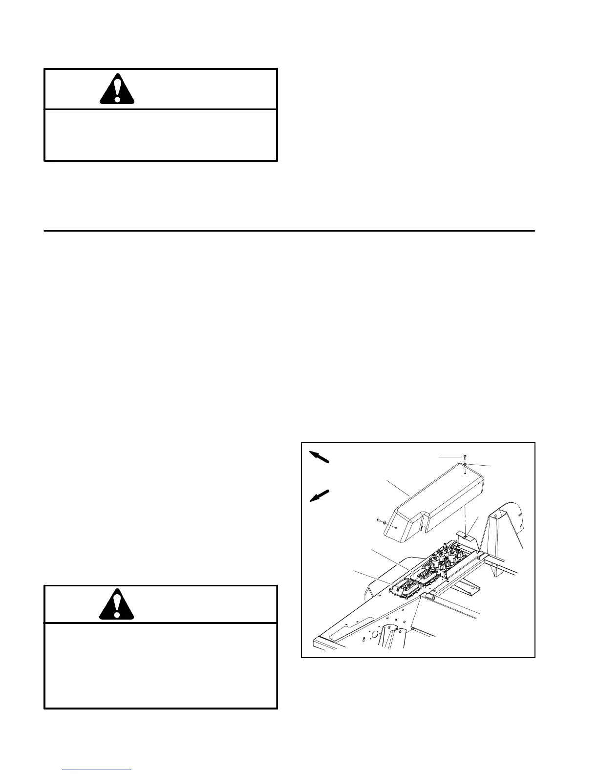
2. Remove the c ontroller cover to allow access to wire
harness loopback connector (Fig. 8). Locate wire har-
ness communication port and loopback connector.
Carefullyunplugloopbackconnectorfromharnesscon-
nector.
3. Connect the Diagnostic Display connector to the
wire harness connector. Make sure correct overlay de-
cal is positioned on the Diagnostic Display (Figs. 9 and
10).
1. Controller cover
2. Screw (2 used)
3. Flat washer (2 used)
4. U--nut (2 used)
5. TEC--5001
6. TEC--5002
Figure 8
FRONT
RIGHT
2
3
1
4
6
5
 Loading...


