Groundsmaster 4100--D/4110--D Page 5 -- 31 Electrical System
Start and Air Conditioning (Groundsmaster 4110--D) Relays
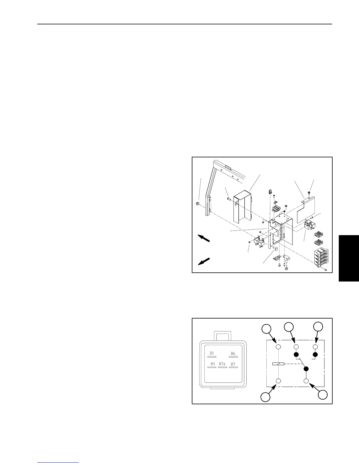
When energized by the TEC--5002 controller, the start
relayisusedtoprovidecurrenttotheenginestartermo-
tor solenoid. The TEC--5002 controls and monitors the
operation of the start relay. The start relay is located at
the power center behind the operator seat (Fig. 36).
An identical relay is used to control the air conditioning
electrical power circuit on the Groundsmaster 4110--D.
Whenenergizedbytheairconditioningswitch,therelay
provides current for the air conditioning components.
The relay is attached to the evaporator assembly in the
cab headliner.
Testing
1. Park machine on a level surface,lowercuttingdeck,
stop engine, engage parking brake and remove key
from the ignition switch. Raise and support hood.
2. Tomakesurethatmachineoperationdoesnotoccur
unexpectedly, disconnect negative (--) cable from bat-
tery and then disconnect positive (+) cable from battery
(seeBattery Service in the Service and Repairs section
of this chapter).
3. Remove cover ( item 1) andheatshield (item 9) from
powercenterandlocaterelaytobetested.Ifnecessary,
removetwo(2)flangenuts andcarriagescrewsthatse-
cure power center to tank support.
4. Disconnect wire harness connector from relay. Re-
move relay from mounting bracket for testing.
NOTE: Prior to taking small resistance readings with a
digital multimeter, short the meter test leads together.
The meter will display a small resistance value (usually
0.5 ohms or less). This resistance is due to the internal
resistanceof themeter andtestleads.Subtract thisval-
uefrom from the measuredvalue ofthecomponent you
are testing.
5. Using a multimeter, verify that coil resistance be-
tween terminals 85 and 86 is from 71 to 88 ohms.
6. Connectmultimeter(ohmssetting)leadstorelayter-
minals 30 and 87. Ground terminal 86 and apply +12
VDC to terminal 85. The relay terminals 30 and 87
shouldhavecontinuityas+12VDCisappliedtoterminal
85.Therelayterminals30and87shouldnothaveconti-
nuity as +12 VDC is removed from terminal 85.
7. Disconnect voltage from terminal 85 and multimeter
lead from terminal 87.
8. Connectmultimeter(ohmssetting)leadstorelayter-
minals 30 and 87A. With terminal 86 grounded, apply
+12VDCtoterminal85.Therelayterminals30and87A
shouldnothave continuity as +12 VDC is applied toter-
minal 85. The relay terminals 30 and 87A should have
continuity as +12 VDC is removed from terminal 85.
9. Disconnect voltage and multimeter test leads from
the relay terminals. Replace relay if necessary.
10.Secure relay to mounting bracket and connect wire
harnessconnectortorelay.Securepowercentertotank
supportifitwasremoved.Installcover(item1) andheat
shield (item 9) to power center.
11.Connect positive (+) cable to battery and then con-
nect negative (--) c able to battery (see Battery Service
in the Service and Repairs section of this chapter).
12.Lower and secure hood.
Figure 36
2
3
4
5
1
8
7
6
9
10
1. Cover
2. Screw
3. Flange nut (2 used)
4. Carriage screw (2 used)
5. Screw
6. Mount
7. Lock nut
8. Start relay
9. Heat shield
10. Screw (2 used)
FRONT
RIGHT
Figure 37
86
85
87A 87
30
2
1
3
4
1. Coil terminal
2. Common terminal
3. Normally closed term.
4. Normally open term.
1
Electrical
System
 Loading...


