Rev. A
Groundsmaster 4100 --D/4110--D Page 5 -- 43 Electrical System
Engine Coolant and Hydraulic Oil Temperature Senders
The Groundsmaster 4100--D and 4110--D use two (2)
temperature senders as inputs for the TEC--5002 to
identify if either the engine coolant or hydraulic oil tem-
perature has reached an excessive level. These send-
ers are identical. The coolant temper ature sender
threads intotheradiator (Fig.57). The hydraulic oil tem-
perature sender is attached to the hydraulic hydraulic
tube on the left side of the machine (Fig. 58).
Testing
1. Locate temperature sender that is to be tested. Dis-
connect wire harness connector from sender.
2. T horoughly clean area around temper ature sender
and remove sender.
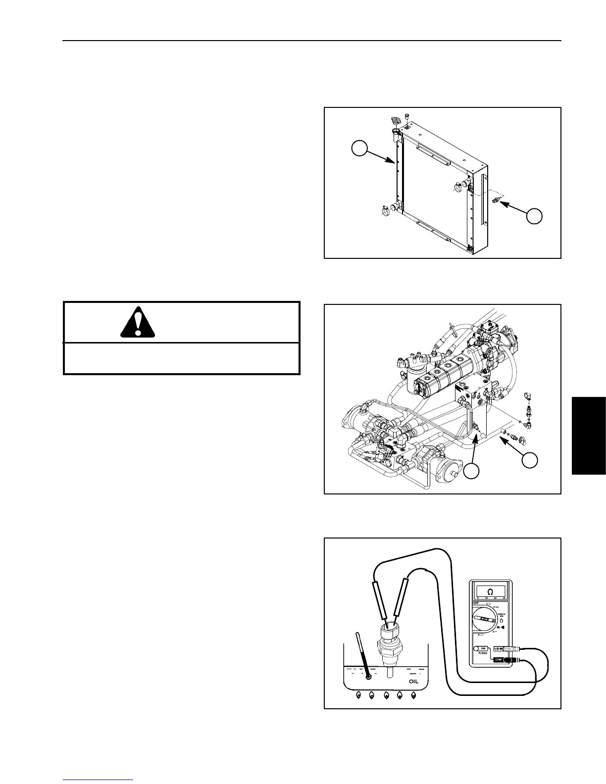
3. Put sensing end of sender in a container of oil with
a thermometer and slowly heat the oil (Fig. 59).
CAUTION
Handle the hot oil with extreme care to prevent
personal injury or fire.
NOTE: Prior to taking resistance readingswith a digital
multimeter ,short the metertestleadstogether. The me-
ter will display a small resistance value (usually 0.5
ohms or less). This resistance is due to the internal re-
sistance of the meter and test leads. Subtract this value
fromfromthemeasuredvalueofthecomponentyouare
testing.
4. Check resistance of the sender with a multimeter
(ohms setting) as the oil temperature increases.
A. T he meter should indicate from 11.6 to 13.5 kilo
ohms at 68
o
F(20
o
C).
B. The meter should indicate from 2.3 to 2.5 kilo
ohms at 140
o
F(60
o
C).
C. The meter should indicate from 605 to 669 ohms
at 212
o
F(100
o
C).
D. Replace sender if specifications are not met.
5. After allowing the sender to cool, install sender:
A. Install new O--ring on sender.
B. Installsenderintoportandtorquefrom9to11ft--
lb (12.3 to 14.9 N--m).
C. Reconnect harness wire to sender.
6. Checkandfillsystem(coolantorhydraulic)toproper
level.
1. Radiator 2. Coolant temp sender
Figure 57
1
2
Figure 58
1. Hydraulic tube 2. Oil temp sender
1
2
Figure 59
Electrical
System
 Loading...


