Groundsmaster 4100--D/4110--D Page 3 -- 15 Kubota Diesel Engine
15.Connect hoist or lift to the lift tabs on engine.
16.Remove flange nuts, rebound washers and cap
screws securing the engine mounts to the engine sup-
ports.
CAUTION
One person should operate lift or hoist while
another person guides the engine out of the ma-
chine.
IMPORTANT: Make sure to not damage the engine,
fuel hoses, hydraulic lines, electrical harness or
other components while removing the engine.
17.Slowly remove engine assembly from the machine.
18.Ifnecessary,removeenginemountsfromtheengine
using Figure 10 as a guide.
Engine Installation (Fig. 10)
1. Make sure that all parts removed from the engine
duringmaintenanceorrebuildingareinstalledtotheen-
gine.
2. Ifremoved,installenginemountstotheengineusing
Figure 10 as a guide.
3. Connect hoist or lift to the engine lift tabs.
CAUTION
One person should operate lift or hoist while
another person guides the engine into the ma-
chine.
IMPORTANT: Make sure to not damage the engine,
fuel hoses, hydraulic lines, electrical harness or
other parts while installing the engine.
4. Carefully lower engine into the machine.
5. Align engine to the engine supports and hydraulic
pumpinputshaft.Secureenginetoenginesupportswith
cap screws, rebound washers and flange nuts.
6. Secure hydraulic pump assembly to engine (see
Pump Assembly Installation in the Service and Repairs
section of Chapter 4 -- Hydraulic System).
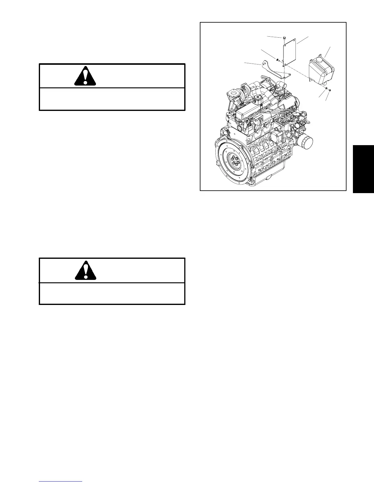
Figure 16
1. Washer reservoir
2. Reservoir mount
3. Carriage screw (3 used)
4. Washer (3 used)
5. Nut (3 used)
6. Flange head screw
7. Exhaust mount
2
3
4
6
7
1
5
7. Install cooling fan motor and fan assembly (Fig. 15).
A. Carefullypositionfanmotor,fanandmotorbrack-
et assembly to radiator.
B. Secure fan motor bracket to radiator with six (6)
cap screws and flange nuts.
C. Remove caps and plugs that were placed in
hosesandfittingsduringremovaltopreventcontam-
ination.
D. Connect hydraulic hoses to cooling fan motor
(see Hydraulic Hose and Tube Installation in the
GeneralInformationsectionofChapter4--Hydraulic
System).
8. Position upperradiator shroudandcoolantreservoir
withbrackettotheradiator.Secureshroudandreservoir
bracket to the radiator and lower radiator bracket with
removedfasteners(seeRadiatorInstallationinthissec-
tion).Makesurethatclearancebetweenshroudandfan
is at least 0.180” (4.6 mm) at all points.
Kubota
Diesel Engine
 Loading...


