Groundsmaster 4100--D/4110--D Page 5 -- 27 Electrical System
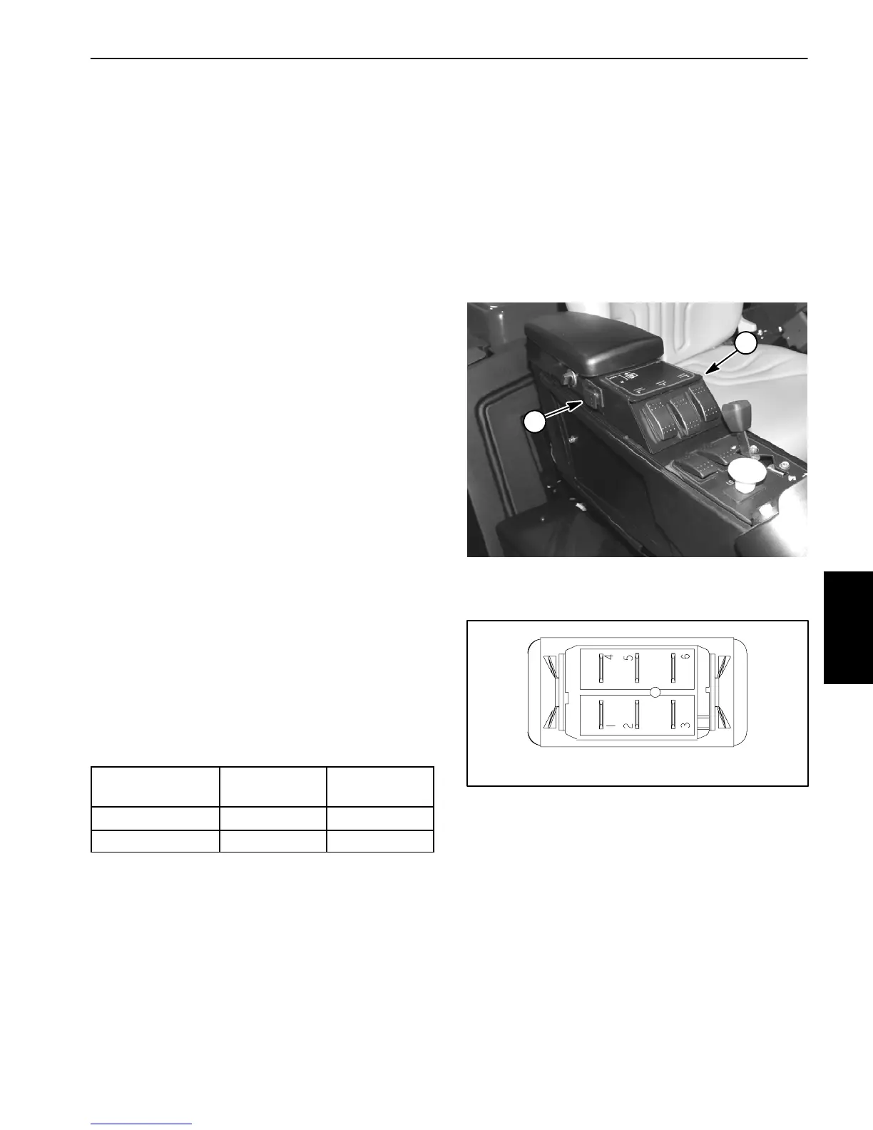
Engine Cooling Fan Switch
Theenginecoolingfanswitchisatwo(2)positionrocker
switch that is located on the outside of the control con-
sole (Fig. 30). The switch has a normal and a momen-
tary position.
Theenginecoolingfanswitchisusedas aninputforthe
TEC--5002 controller to allow the engine cooling fan to
run in the normal, automatic mode or in the manual re-
verse (momentary) direction.
Testing
1. Before disconnecting the engine cooling fan switch
for testing, the switch and its circuit wiring should be
testedasaTEC--5002 inputwiththeDiagnosticDisplay
(see Diagnostic Display in the Troubleshooting section
of this chapter). If the D iagnostic Display verifies that
switchandcircuitwiringarefunctioningcorrectly,nofur-
therswitchtestingisnecessary.If,however,theDisplay
determines that the switch and circuit wiring are not
functioning correctly, proceed with test.
2. Make sure ignition switch is OFF. Remove key from
ignition switch.
3. Disassembleconsolearmtogainaccesstothecool-
ing fan switch (see Console Arm Disassembly in the
Service and Repairs section of Chapter 7 -- Chassis).
4. Disconnect wire harness electrical connector from
the switch.
5. With the use of a multimeter (ohms setting), the
switch functions may be tested to determine whether
continuityexists betweenthe variousterminalsforeach
switch position. The switch terminals are marked as
shown in Figure 31. The circuitry of the cooling fan
switch is shown in the chart below. Verify continuity be-
tween switch terminals.
SWITCH
POSITION
NORMAL
CIRCUITS
OTHER
CIRCUITS
NORMAL 2+3 5+6
MOMENTARY 2+1 5+4
6. If switch tests correctly and circuit problem still ex-
ists,checkwireharness(seeElectricalSchematicsand
Wire Harness Drawings in Chapter 10 -- Foldout Draw-
ings).
7. After testing is completed, connect wire harness
connector to the switch.
8. Assembleconsolearm(seeConsoleArmAssembly
inthe Serviceand Repairssectionof Chapter7 -- Chas-
sis).
1. Console arm 2. Cooling fan switch
Figure 30
1
2
Figure 31
BACK OF SWITCH
NOTE: Only cooling fan switch terminals 1 and 2 are
used on Groundsmaster 4100-- D and 4110 --D ma-
chines.
Electrical
System
 Loading...


