Groundsmaster 4100--D/4110--D Page 5 -- 41 Electrical System
Traction Neutral Switch
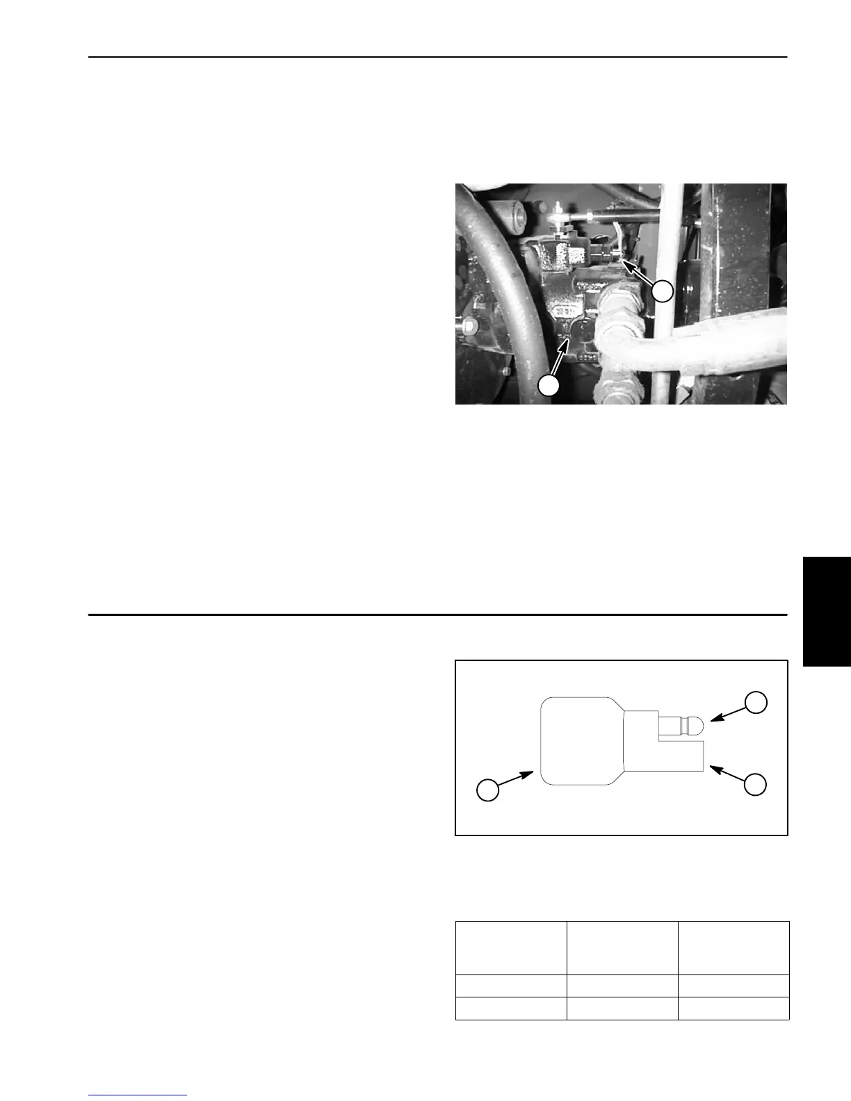
The traction neutral switch is closed when the traction
pedalisintheneutralpositionandopenswhenthepedal
isdepressedineitherdirection(forwardorreverse).The
neutralswitchisusedasaninputtotheTEC--5002 con-
troller. The switch is located on the right side of the pis-
ton (traction) pump (Fig. 53).
Testing
Beforedisconnectingthetractionneutralswitchfortest-
ing, the switch and its circuit wiring should be tested as
a TEC--5002 input with the Diagnostic Display (see
DiagnosticDisplayintheTroubleshootingsectionofthis
chapter). If the Diagnostic Display verifies that the neu-
tralswitchandcircuitwiringarefunctioningcorrectly,no
further switch testing is necessary. If, however, the Dis-
playdeterminesthattheneutralswitchandcircuitwiring
are not functioning correctly, proceed with test.
Test the neutral switch by disconnecting the wires from
theswitchterminalsandconnectingamultimeter(setto
ohms) across the two (2) switch terminals. With the en-
gine turned off, slowly push the traction pedal in a for-
wardorreversedirectionwhilewatchingthemultimeter.
There should be indications that the traction neutral
switch is opening (high resistance) and closing (low re-
sistance).Allowthetractionpedaltoreturntotheneutral
position. There should be continuity (low resistance)
acrossthe switchterminals whenthe tractionpedalisin
the neutral position.
See the Eaton Model 72400 Servo Controlled Piston
Pump Repair Information at the end of Chapter 4 -- Hy-
draulic System for disassembly and assembly proce-
dures for the traction neutral switch.
1. Piston pump (bottom) 2. Neutral switch
Figure 53
1
2
Diode Assembly
The Groundsmaster engine wire harness contains a
diode that is used for circuit protection from voltage
spikes when the engine starter solenoid is de--ener-
gized.Thediodeplugsintothewireharnessneartheen-
ginestartermotor(seeEngineWireHarnessDrawingin
Chapter 10 -- Foldout Drawings).
Testing
The diode can be tested using a digital multimeter
(diode test or ohms setting) and the chart to the right.
Figure 54
1. Diode
2. Male terminal
3. Female terminal
1
3
2
Multimeter
Red Lead (+)
on Terminal
Multimeter
Black Lead (--)
on Terminal
Continuity
Female Male YES
Male Female NO
Electrical
System
 Loading...


