Groundsmaster 4100--D/4110--DPage 5 -- 24Electrical System
PTO Switch
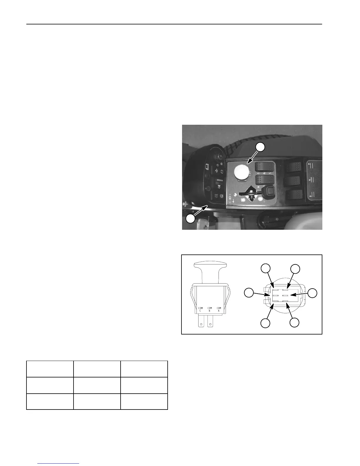
ThePTOswitchis located on the console arm (Fig.24).
The PTO switch is pulled up to engage the PTO and
pushed in to disengage the PTO.
The TEC--5001 controller monitors the position of the
PTO switch (up or down). Using inputs from the PTO
switch and other switches in the interlock system, the
TEC--5001 controller c ontrols the energizing of the hy-
draulic solenoid valves used to drive the cutting deck
motors.
NOTE: To engage the PTO, the seat has to be occu-
pied, traction speed has to be in Low range (4WD) and
the cutting deck has to be fully lowered.
Testing
1. Before disconnecting the PTOswitch for testing,the
switch and its circuit wiring should be tested as a
TEC--5001 input with the Diagnostic Display (see Diag-
nostic Display in the Troubleshooting section of this
chapter). If the Diagnostic Display verifies that the PTO
switchandcircuitwiringarefunctioningcorrectly,nofur-
therswitchtestingisnecessary.If,however,theDisplay
determines that the PTO switch and circuit wiring are
not functioning correctly, proceed with test.
2. Make sure ignition switch is OFF. Remove key from
ignition switch.
3. Disassemble console arm to gain access to PTO
switch (see Console Arm Disassembly in the Service
and Repairs section of Chapter 7 -- Chassis).
4. Disconnect harness electrical connector from the
PTO switch.
5. The switchterminalsare markedasshown inFigure
25. The circuit logic of the PTO switch is shown in the
chartbelow.Withtheuseofamultimeter(ohmssetting),
theswitchfunctionscanbetestedtodeterminewhether
continuityexists betweenthe variousterminalsforeach
switch position. Verify continuity between switch termi-
nals. Replace switch if testing identifies that switch is
faulty.
SWITCH
POSITION
CLOSED
CIRCUITS
OPEN
CIRCUITS
OFF (DOWN) COM B + NC B
COM C + NC C
COM B + NO B
COM C + NO C
ON (UP) COM B + NO B
COM C + NO C
COM B + NC B
COM C + NC C
6. If PTO switch tests correctly and circuit problem still
exists, check wire harness (see Electrical Schematics
and Wire Harness Drawings in Chapter 10 -- Foldout
Drawings).
7. After testing is completed, connect the wire harness
connector to the PTO switch.
8. Assembleconsolearm(seeConsoleArmAssembly
inthe Serviceand Repairssectionof Chapter7 -- Chas-
sis).
1. PTO switch 2. Control console
Figure 24
1
2
1. COM B terminal
2. NO B terminal
3. NC B terminal
4. COM C terminal
5. NO C terminal
6. NC C terminal
Figure 25
2
3
1
6
4
5
NOTE: Only PTO switch terminals COM C and NO C
are used on Groundsmaster 4100--D and 4110--D ma-
chines.
 Loading...


