Groundsmaster 4100--D/4110--DPage 5 -- 42Electrical System
Wing Deck Position Switches
Two (2) wing deck position switches are used on the
Groundsmaster 4100--D and 4110--D as inputs for the
TEC--5001 controller. The position switches are pow-
ered proximity switches that are normally open. The
switchesincorporateaninternalreedswitchandaLED.
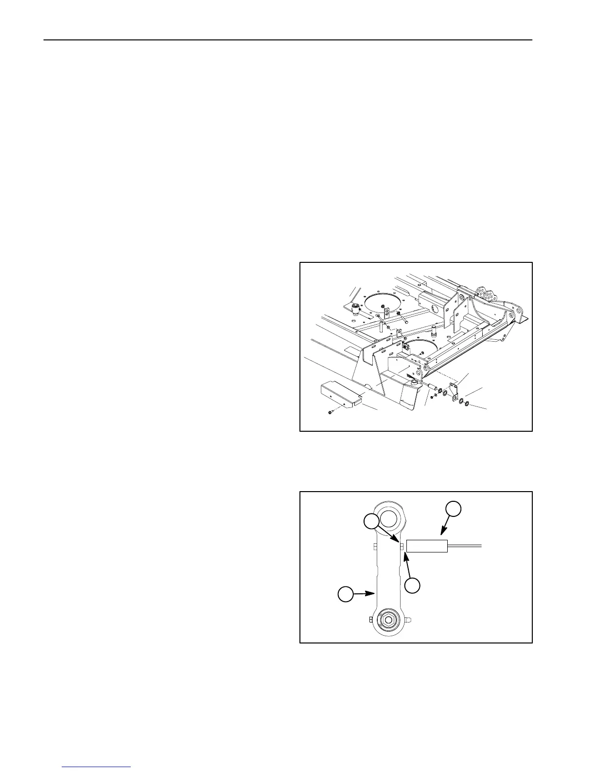
Theseswitches are secured to thecenter section of the
cutting deck (Fig. 55). A bolt head on the wing deck link
is the sensing plate for the position switch (Fig. 56).
Whenawing deck is lowered, the bolt head on the wing
decklink is positionedcloseto thepositions witch caus-
ing the switch to close. The closed switch provides an
inputfortheTEC--5001controllertoallowwingdeckop-
eration.Whenawingdeckisraised,theboltheadonthe
wing deck link is moved away from the position switch
sotheswitchisinitsnormallyopenstate.Theopenposi-
tionswitchpreventswingdeckoperationwhen thewing
deck is raised.
Testing
1. The cutting deck position switches and their circuit
wiring should be tested as a TEC--5001 input with the
Diagnostic Display (see Diagnostic Display in the Trou-
bleshooting section of this chapter). If the Diagnostic
Displayverifiesthatthepositionswitchesandcircuitwir-
ing are functioning correctly,no further switch testing is
necessary. If, however, the Display determines that a
positionswitchandcircuitwiringarenotfunctioningcor-
rectly, proceed with test.
2. Park machine on a level surface, lower cutting deck
(including wing decks), stop engine and apply parking
brake. Remove switch cover from deck to allow access
to switch that requires testing (Fig. 55).
3. Turn ignition switch to the ON position (do not start
engine) and check LED on cable end of position
switches. LED should be illuminated when the wing
decks are fully lowered.
4. Startengine,fullyraisewingdecksandthenstopen-
gine.Then,turnignitionswitchtotheONposition(donot
start engine) and check LED on cable end of position
switches.LEDshouldnotbeilluminatedwhenthewing
decks are fully raised.
5. Lower wing decks and then stop engine.
6. If a position switch LED did not function correctly:
A. MakesurethatignitionswitchisOFFanddiscon-
nect the switch connector from deck wire harness.
B. Using a multimeter, verify that wire harness con-
nector terminal for pink wire has 12 VDC when the
ignition switch is ON.
C. Make sure that gap between end of position
switchandboltheadonwingdecklinkwhenthew ing
deck is lowered is from 0.070” to 0.130” (1.8 to 3.3
mm) (Fig. 56).
D. Ifpinkwirehassystemvoltagepresentandgapis
correctbutswitchLEDdidnotfunction,replaceposi-
tion switch.
7. After testing iscomplete,make sure thatswitch con-
nector is plugged into deck wire harness. Install switch
cover to deck.
1. Switch cover
2. Position switch
3. Switch bracket
4. Lock washer (2 used)
5. Jam nut (2 used)
Figure 55
1
2
3
4
5
1. Position switch
2. Bolt head
3. Wing deck link
4. Gap location
Figure 56
1
2
3
4
 Loading...


