Groundsmaster 4100--D/4110--D Page 5 -- 29 Electrical System
Parking Brake Switch
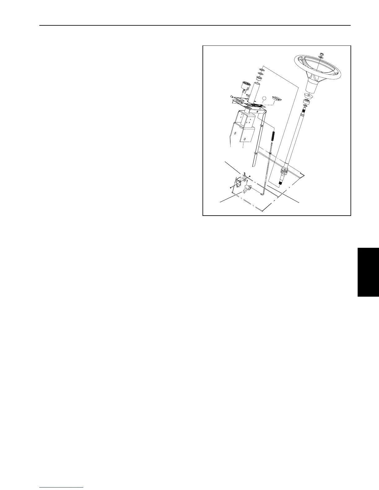
Theswitchusedfortheparkingbrakeisanormallyopen
switch that is located under the steering tower cover
(Fig. 33). The brake switch is used as an input for the
TEC--5002controller.Whentheparkingbrakeisnotap-
plied, the parking brake pawl depresses the switch
plunger to close the switch. When the parking brake is
applied,the parkingbrake pawlispositioned awayfrom
the switch plunger so the switch is in its normal, open
state.
Testing
1. Before disconnecting the parking brake switch for
testing,theswitch and itscircuit wiringshouldbetested
as a TEC--5002 input with the Diagnostic Display (see
DiagnosticDisplayintheTroubleshootingsectionofthis
chapter).IftheDiagnosticDisplayverifiesthatthebrake
switchandcircuitwiringarefunctioningcorrectly,nofur-
therswitchtestingisnecessary.If,however,theDisplay
determines that the brake switch and circuit wiring are
not functioning correctly, proceed with test.
2. Make sure ignition switch is OFF. Remove key from
ignition switch.
3. Locateparkingbrakeswitchfortesting(seeSteering
Tower Disassembly in the Service and Repairs section
of Chapter 7 -- Chassis).
4. Disconnect wire harness connector from the brake
switch.
5. Check the continuity of the s witch by connecting a
multimeter (ohms setting) across the connector termi-
nals.
6. When the brake switch plunger is extended there
should not be continuity between the switch terminals.
7. When the brake switch plunger is depressed, there
should be continuity between the switch terminals.
8. After testing, connect wire harness connector to
parking brake switch.
9. Secureallremovedsteeringtowercomponents(see
Steering Tower Assembly in the Service and Repairs
section of Chapter 7 -- Chassis).
1. Parking brake switch
2. Parking brake rod
3. Parking brake pawl
Figure 33
2
3
1
Electrical
System
 Loading...


