Groundsmaster 4100--D/4110--D Page 5 -- 7 Electrical System
4. TurntheignitionswitchtotheONposition,butdonot
start machine.
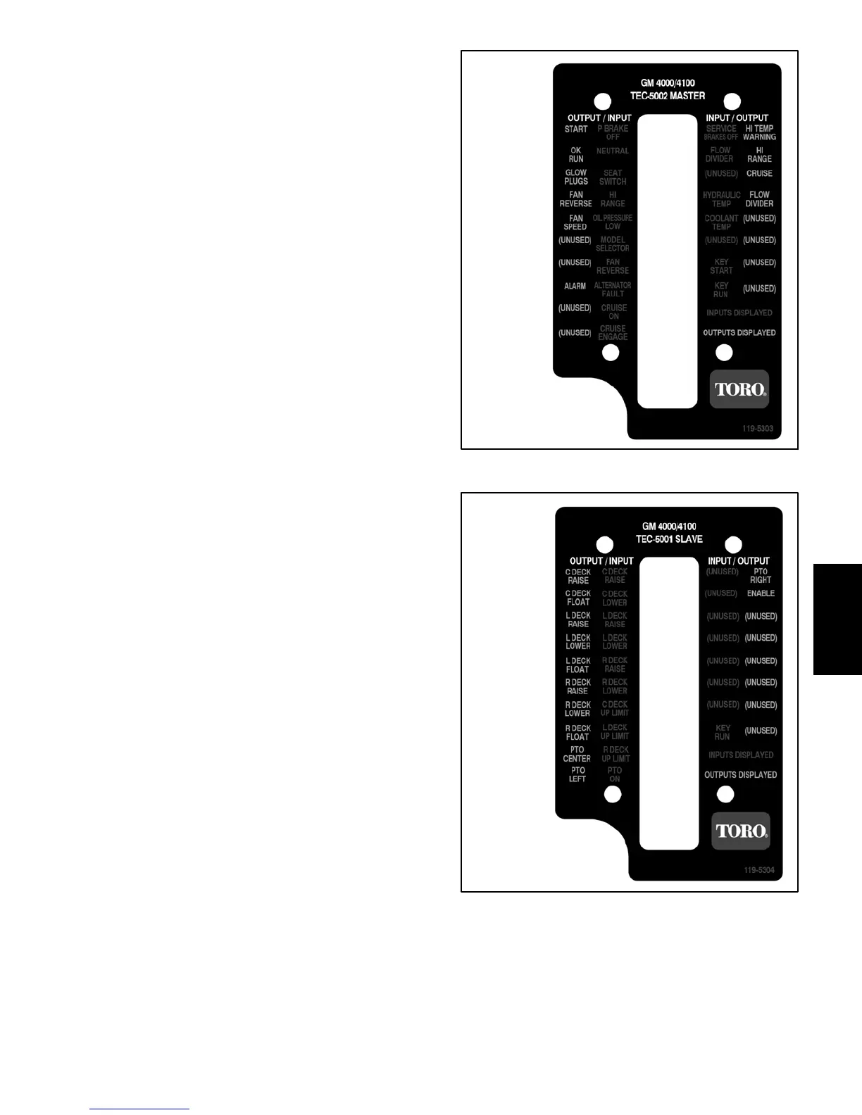
NOTE: The red text on the Diagnostic Display overlay
decal refers to input switches and the green text refers
to TEC outputs.
5. Make sure that the “INPUTS DISPLAYED” LED, on
lower right column of the D iagnostic Display, is illumi-
nated. If “OUTPUTS DISPLAYED” LED is illuminated,
press the toggle button on the Diagnostic Display to
change to “INPUTS DISPLAYED” LED.
6. The Diagnostic Display will illuminate the LED
associatedwitheachoftheinputswhenthatinputswitch
isclosed.Individually,changeeachoftheswitchesfrom
open to closed (i.e., sit on seat, press traction pedal,
etc.),andnotethattheappropriateLEDontheDiagnos-
ticDisplaywillilluminatewhenthecorrespondingswitch
is closed. Repeat on each switch that is possible to be
changed by hand (see Inputs and LED Operation chart
on following page).
NOTE: When the Diagnostic Display is attached to the
wire harness connector and the ignition switch is in the
ON position, the input LED for hydraulic temp and cool-
anttempshouldbeilluminated.Iftheharnessconnector
is disconnected from the sensor for either of these in-
puts, the appropriate LED s hould go off after a few sec-
ond delay. Then, if the harness connector is reattached
tothesensor,theinputLEDshouldagainilluminateafter
a few seconds.
7. If appropriate LED does not toggle on and off when
switch state is changed, check all wiring and connec-
tions to that switch and/or test switch (see Component
Testinginthischapter).Replace anydefectiveswitches
and repair any damaged wiring.
8. After input functions testing is complete, disconnect
theDiagnosticDisplayconnectorfromtheharnesscon-
nector and plug loopback connector into wire harness.
Secure controller cover to machine.
Figure 9
TEC--5002
MASTER
OVERLAY
Figure 10
TEC--5001
SLAVE
OVERLAY
Electrical
System
 Loading...


