Groundsmaster 4100--D/4110--D Hydraulic SystemPage 4 -- 109
Removal (Fig. 73)
1. Park machine on a level surface,lowercuttingdeck,
stop engine, engage parking brake and remove key
from the ignition switch.
2. Read the General Precautions for Removing and
Installing Hydraulic System Components at the begin-
ning of this section.
3. Topreventcontaminationofhydraulicsystemduring
steering control valve removal, thoroughly clean exteri-
or of control valve and fittings.
NOTE: To ease installation, label the hydraulic lines to
showtheircorrectpositiononthesteeringcontrolvalve.
4. Remove hydraulic lines from steering control valve.
5. Remove steering control valve from machine using
Figure 73 as a guide.
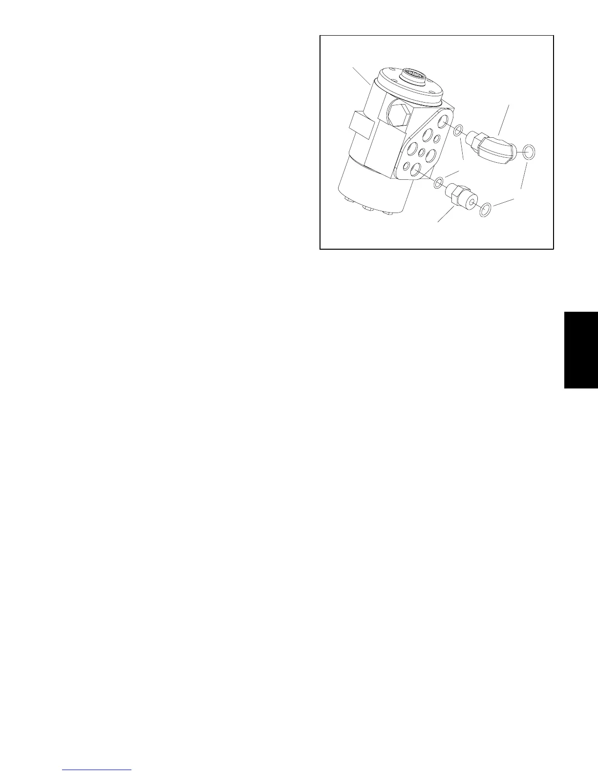
6. If hydraulic fittings are to be r emoved from steering
controlvalve,markfittingorientationtoallowcorrectas-
sembly(Fig.74).Removefittingsfromcontrolvalveand
discard O--rings.
Installation (Fig. 73)
1. If fittings were removed from steering control valve,
lubricate and place new O--rings onto fittings. Install fit-
tingsintoportopeningsusingmarksmadeduringthere-
moval process to properly orientate fittings (Fig. 74).
Tighten fittings (see Hydraulic Fitting Installation in the
General Information section of this chapter).
2. Install steering control valve using Figure 73 as a
guide.
3. Using labels placed duringsteeringcontrolvalvere-
moval, properly install hydraulic lines to control valve
(seeHydraulicHoseandTubeInstallationin theGener-
al Information section of this chapter).
4. Makesurehydraulictankisfull.Addcorrectoilifnec-
essary before returning machine to service.
1. Steering control valve
2. O--ring
3. 90
o
hydraulic fitting
4. O--ring
5. Straight fitting (4 used)
Figure 74
1
2
4
5
3
Hydraulic
System
 Loading...


