Groundsmaster 4100--D/4110--D Page 5 -- 33 Electrical System
Testing
1. Park machine on a level surface,lowercuttingdeck,
stop engine, engage parking brake and remove key
from the ignition switch.
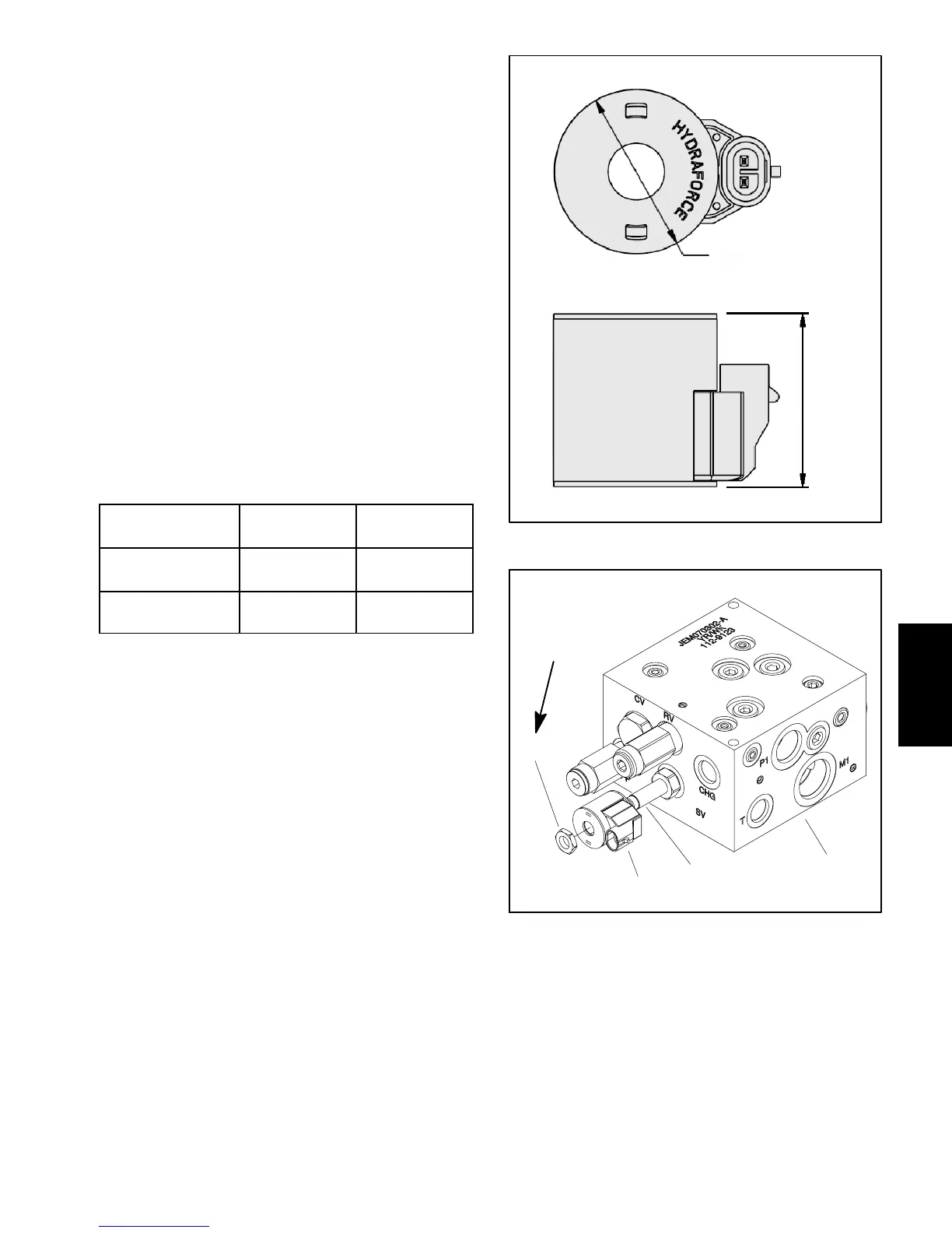
2. Locatehydraulicvalvesolenoidcoiltobetested(Fig.
38). Disconnect wire harness connector from coil.
3. Identify coil resistance specification by measuring
the coil diameter and coil height (Fig. 39).
NOTE: Prior to taking small resistance readings with a
digital multimeter, short the meter test leads together.
The meter will display a small resistance value (usually
0.5 ohms or less). This resistance is due to the internal
resistanceof themeter andtestleads.Subtract thisval-
uefrom from the measuredvalue ofthecomponent you
are testing.
4. Using a multimeter (ohms setting), measure resis-
tance between the two (2) connector terminals on the
solenoidcoil.Thecorrectresistanceforthesolenoidcoil
is identified in the chart below.
COIL
DIAMETER
COIL
HEIGHT
COIL
RESISTANCE
1.84 in
(46.7 mm)
1.96 in
(49.9 mm)
7.1 ohm
1.41 in
(35.8 mm)
1.43 in
(36.3 mm)
8.8 ohm
NOTE: Solenoid coil resistance should be measured
withsolenoidatapproximately68
o
F(20
o
C).Resistance
maybe slightly differentthanlisted atdifferenttempera-
tures. Typically, a failed solenoid coil will either be
shorted (very low or no resistance) or open (infinite re-
sistance).
5. If solenoid coil r esistance is incorrect, replace coil:
A. Remove nut securing solenoid coil to the car-
tridge valve. Carefully slide solenoid coil off the
valve.
B. Install new solenoid c oil to the cartridge valve.
Install and torque nut 5ft--lb(6.7N--m).Over--tight-
ening may damage the s olenoid c oil or cause the
cartridge valve to malfunction.
6. After testing is completed, connect wire harness
connector to the solenoid coil.
Figure 39
COIL
DIAMETER
COIL
HEIGHT
1. Hydraulic manifold
2. Cartridge valve
3. Solenoid coil
4. Nut
Figure 40
1
2
3
4
5ft--lb
(6.7 N--m)
4WD MANIFOLD
SHOWN
Electrical
System
 Loading...


