Groundsmaster 4100--D/4110--D Cutting DeckPage 8 -- 17
Installation (Fig. 13)
1. Position spindleoncutting deck notingo rientation of
greasefitting(Fig.15).Securespindleassemblytodeck
with removed fasteners.
2. Install cutting blade, anti--scalp cup and blade bolt.
Tighten blade bolt from 88 to 108 ft--lb (119 to 146
N--m).
3. Slowly rotate cutting blades to verify that blades do
not contact any deck component(s).
4. Installdrivebeltandadjustbelttension(seeIdlerAs-
sembly Installation in this section).
5. If drive spindle was removed, install hydraulic motor
to cutting deck (see Cutting Deck Motor Installation in
theServiceandRepairs SectionofChapter4 --Hydrau-
lic System).
IMPORTANT: Pneumatic grease guns can produce
airpocketswhenfilling largecavitiesandtherefore,
are not recommended to be used for proper greas-
ing of spindle housings.
6. Attach a hand pump grease gun to grease fitting on
spindle housing and fill housing cavity with grease until
grease starts to come out of lower seal.
7. Install belt covers to cutting deck.
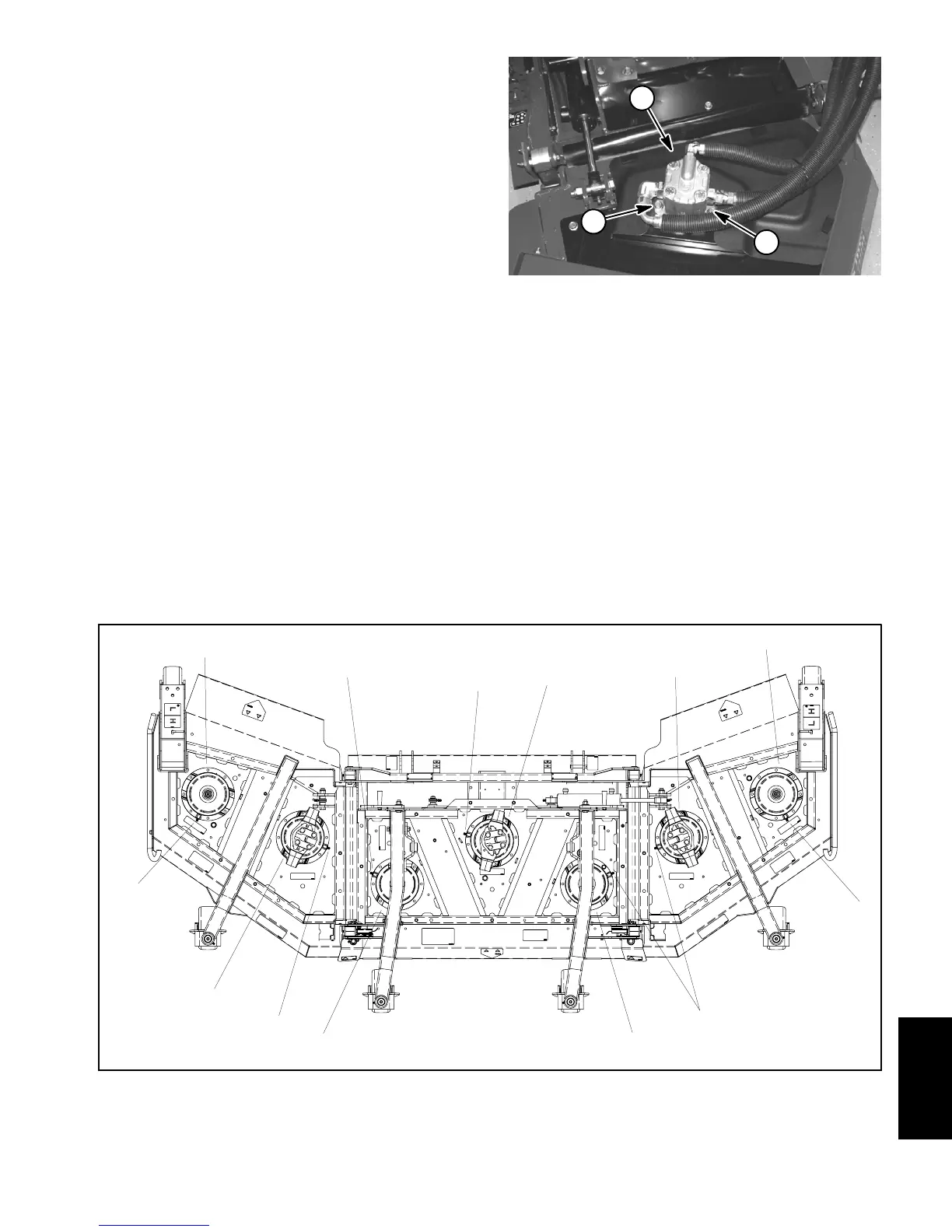
1. Flange head screw 2. Hydraulic motor
Figure 14
1
2
1
1. Driven spindle
2. Driven spindle (high pulley)
3. Drive spindle (wing deck)
4. Drive spindle (center deck)
5. Spindle grease fitting location
Figure 15
5
3
2
5
1
1
4
3
5
1
5
5
5
Cutting
Deck
 Loading...


