Chapter 5 UCM Wiring and Addressing
88 BMTW-SVN01F-EN
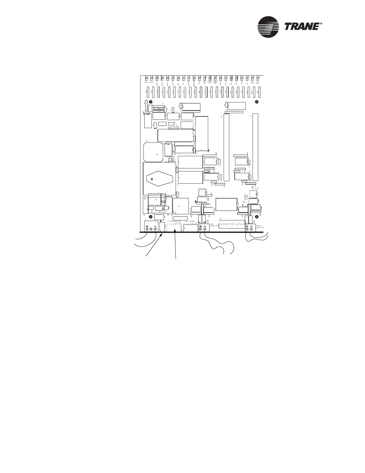
Figure 43. LCP Supervisor Component Layout
To connect the shield:
At the LCP supervisor, splice the shield with the shield of the next section
of the communication-link wiring and tape it to prevent any connection
between shield and ground. You can connect the BCU to the LCP supervi-
sor directly or in a daisy chain configuration with other LCPs. Limit the
total aggregate length of the wiring to each communication link to
5,000 ft (1,524 m). For LCP wiring termination points and procedures,
refer to the lighting control panel literature.
Connect the shield at the BCU (TB2) to provide a drain for RFI/EMI, and
then splice it with other LCP shields at the LCP end. Tape the shield at
the last LCP in the chain to prevent any connection between the shield
and ground (see Figure 44 on page 89).
IMPORTANT
UCM ground loops will cause a malfunction.
24 Vdc Power
from LCP
Reset Switch
Address
DIP Switch
(0–81)
LCP
Communication Link
(requires termination
resistors)
Tracer Summit
Communication
Link

 Loading...


