VariTrane DDC/VAV UCMs Interface
BMTW-SVN01F-EN 127
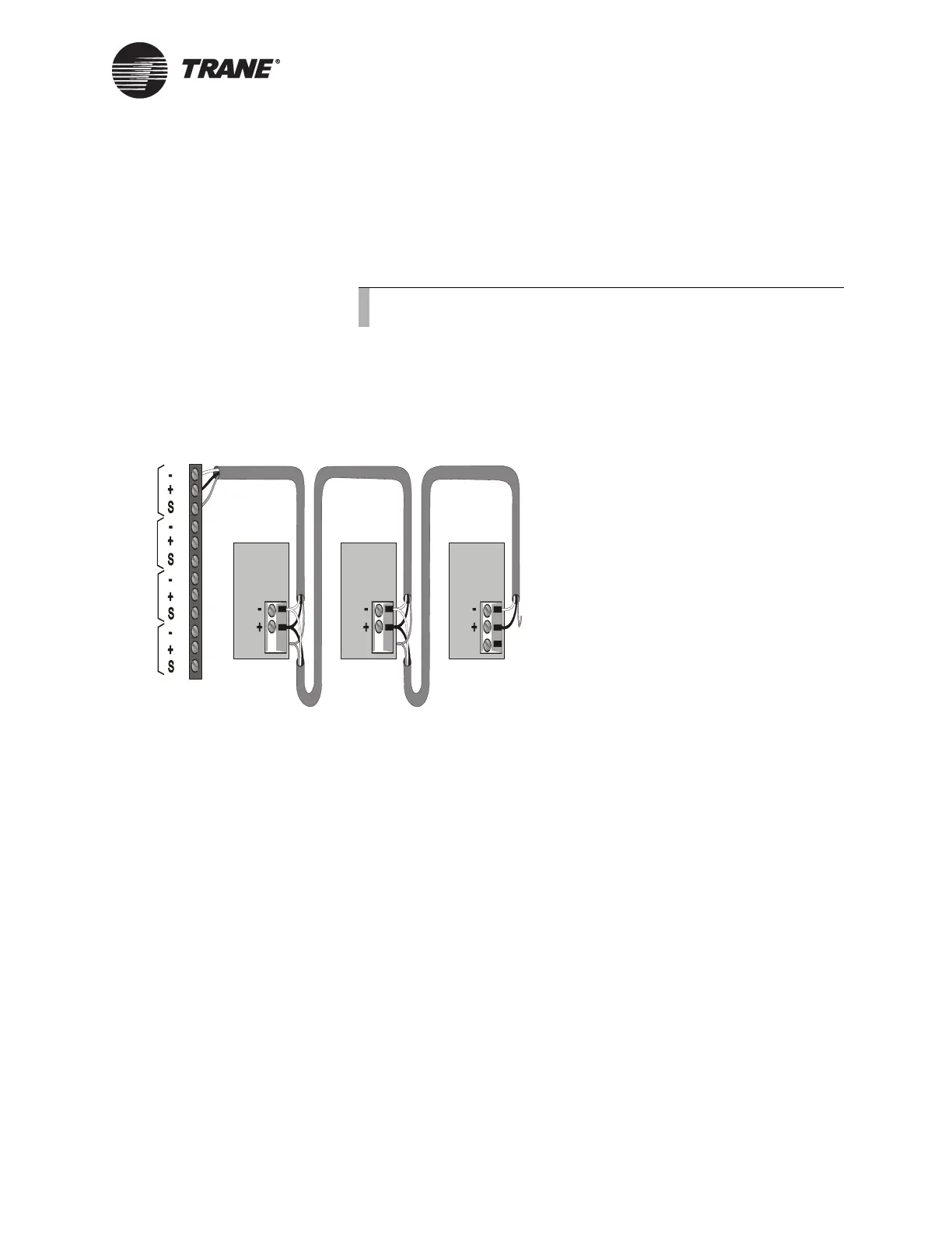
To connect shield:
Connect the shield at the BCU (TB2) to provide a drain for RFI/EMI, and
then splice it with other VAV UCM shields at the VAV UCM end. Tape
the shield at the last VAV UCM in the chain to prevent any connection
between the shield and ground (see Figure 59).
IMPORTANT
UCM ground loops will cause a malfunction.
Figure 59. ICS Connections Between the BCU and VAV II/III/IVs on a
Comm4 Link
Device Addressing
Each UCM must have a unique address on each link. On the UCM, the
address is set with the S1 DIP switch (see Figure 60 on page 128).
• For VAV I and VAV IA DIP switch settings, refer to Table 25 on
page 131.
• For VAV II,VAV III, and VAV IV DIP settings, refer to Table 24 on
page 129.
Note:
Observe the polarity throughout communication links.
Device #3
Comm Link
Terminal Block
Device #1
Cut and tape
the shield
wires together.
Device #2
Cut and tape
the shield
wires together.
Cut and tape
back the
shield wire.
1
2
3
4
5
6
7
8
9
10
11
12
Link 1
Link 2
Link 3
Last device on
the Comm4 link
Shield Shield Shield
Comm Link
Terminal Block
Comm Link
Terminal Block
Link 4

 Loading...


