Lighting Control Panel (LCP) Interface
BMTW-SVN01F-EN 89
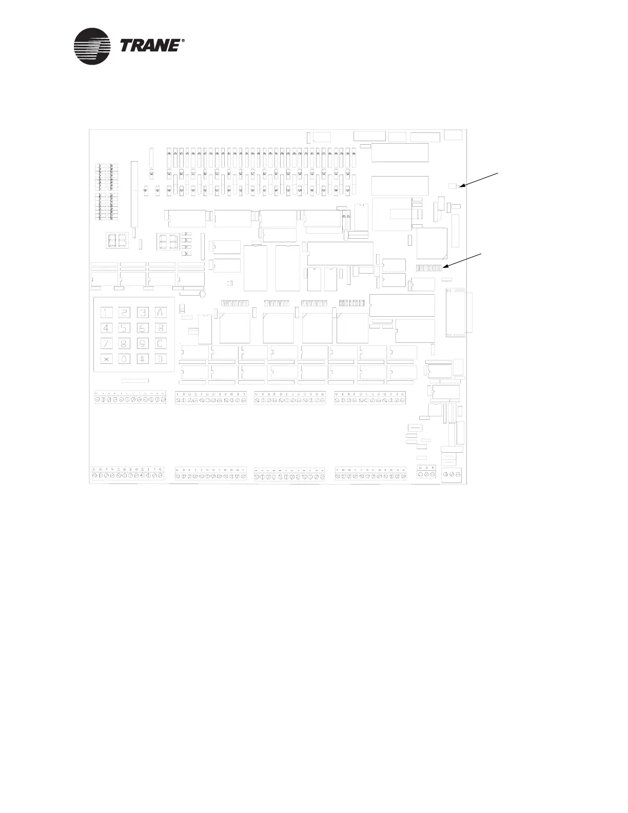
Figure 44. DIP Switch Location on LCP Logic Board
Device Addressing
Each LCP supervisor must have a unique address on the LCP communi-
cation link. The LCP supervisor address is set using a DIP switch on the
LCP supervisor. The supervisor is transparent to the BCU. Each LCP
UCM must also have a unique address that is set using a DIP switch on
the LCP.
Assign each LCP a unique address number by setting the DIP switch
labeled Options Select on the logic board. Switch positions are labeled 1
through 8. Valid LCP addresses range from 82 to 126. Press and release
the reset button after setting the address of the LCP.
• The location of the Tracer Summit address DIP switch on the LCP
supervisor is shown in Figure 43 on page 88.
• The location of the address DIP switch on the LCP is shown in
Figure 44.
Reset Button
Options Select
DIP Switch (for
LCP Address)

 Loading...


