BCU Mounting and Power Wiring for International Installations
BMTW-SVN01F-EN 27
To extend the life of the BCU electronic components, ensure that the
selected location avoids extreme operating conditions (including excessive
vibration) whenever possible.
CAUTION
Avoid Equipment Damage!
Install the BCU in a location that is out of direct sunlight. Failure to do
so may cause the BCU to overheat.
To avoid malfunctions caused by electrical interference, do not install the
BCU near high-power radio signals, electrical switching gear, power
buses, large motors, or other sources of electrical noise.
Verify Conformance to BCU Specifications
Ensure that the location conforms to BCU specifications. BCU specifica-
tions are shown in Table 3 and a dimensional drawing of a BCU is shown
in Figure 4 on page 17.
Verify Conformance to Clearance Specifications
Make sure that the selected location provides enough space to accommo-
date the BCU minimum clearances (see Figure 5 on page 18). The clear-
ances are for ventilation, electrical conduit access, and sufficient human
access for the installing contractor, operator, and service technician:
• The top clearance allows for ventilation and entry of conduit for the
120/240 Vac power supply, low-voltage communications links, and
input/output wiring.
• The bottom clearance allows for the alternate entry of conduit for low-
voltage communication links and input/output wiring. It also allows
for ease of access while making wiring connections. In addition, the
bottom clearance specifies the optimum mounting height for BCUs
with operator displays.
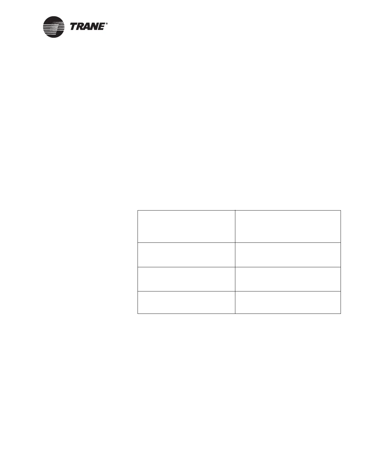
Table 3. Tracer Summit BCU Specifications
Dimensions
Height
Width
Depth
482 mm (19 in.)
406 mm (16 in.)
152 mm (6 in.)
Weight
Without operator display
With operator display
6.8 kg (15.0 lb)
7. 9 k g ( 1 7. 5 l b )
Operating environment
Te m p e r a t ur e
Humidity
0ºC to 50ºC (32ºF to 120ºF)
10–90% noncondensing
Power requirements Switch selectable for 98–132 Vac or
196–264 Vac, 5 A maximum, 1 phase,
50 or 60 Hz

 Loading...


