Chapter 5 UCM Wiring and Addressing
116 BMTW-SVN01F-EN
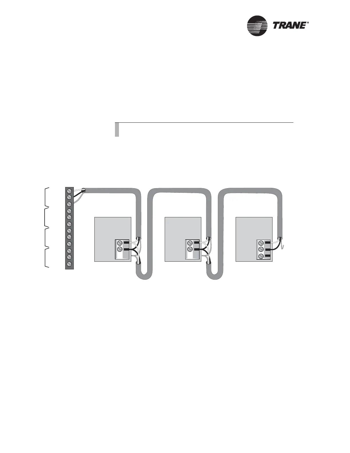
To connect shield:
1. Connect the shield at the BCU (TB2) to provide a drain for RFI/EMI,
and then splice it with other SMM/UCM shields at the SMM/UCM
end.
2. Tape the shield at the last SMM/UCM in the chain to prevent any
connection between the shield and ground (refer to the Trane Europe
chiller installation, operation, and maintenance manual for details).
IMPORTANT
UCM ground loops will cause a malfunction.
Figure 54. ICS Connections Between the BCU and Trane Europe Chiller
Interface
Device Addressing
Each UCM must have a unique address on each link. On the Trane
Europe chiller, addresses are set from the front panel. Refer to the Trane
Europe chiller installation, operation, and maintenance manual for
details.
Note:
Observe the polarity throughout communication links.
SMM #3
+
-
Serial
Communication
Link
SMM #1
Cut and tape
the shield
wires together.
SMM #2
Cut and tape
the shield
wires together.
Cut and tape
back the
shield wire.
1
2
3
4
5
6
7
8
9
10
11
12
+
-
Link 1
S
+
-
Link 2
S
+
-
Link 3
S
+
-
+
-
Last device on
the Comm4 link
Shield Shield Shield
Serial
Communication
Link
Serial
Communication
Link
+
-
Link 4
S

 Loading...


