Voyager Rooftop Unit Interface
BMTW-SVN01F-EN 139
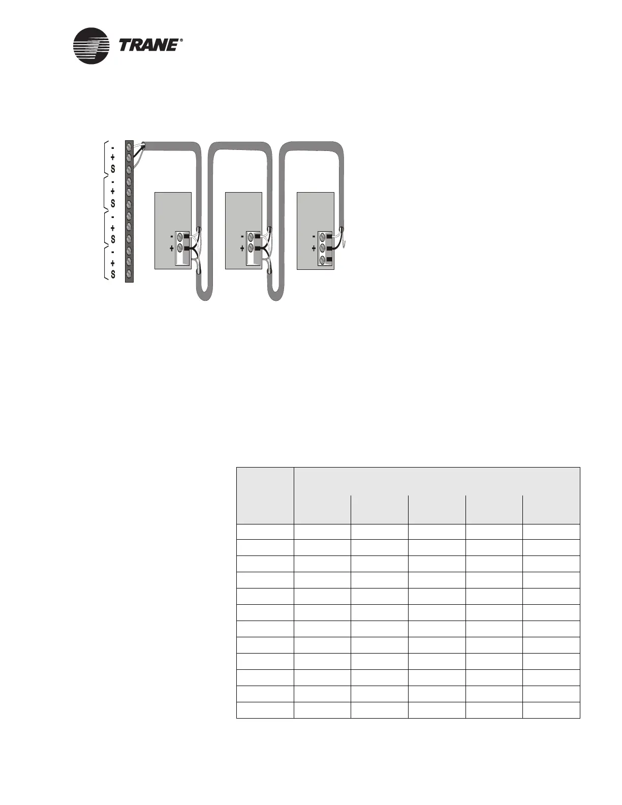
Figure 64. ICS Connections Between the BCU and Voyager Rooftop
Unit UCMs on a Comm3 or Comm4 Link
Device Addressing
Each UCM must have a unique address on each link. Voyagers can have
an address from 50 through 81. The Voyager address is set using DIP
switches on the TCI-3 board and must match the address set in Site Con-
figuration for Tracer Summit. Refer to the TCI-3 literature for more
details about setting the address.
• For the DIP switch locations on the TCI-3 board, see Figure 63 on
page 137.
• For Voyager address DIP switch settings, refer to Table 27.
Device #3
Comm Link
Terminal Block
Device #1
Cut and tape
the shield
wires together.
Device #2
Cut and tape
the shield
wires together.
Cut and tape
back the
shield wire.
1
2
3
4
5
6
7
8
9
10
11
12
Link 1
Link 2
Link 3
Last device on
the Comm4 link
Shield Shield Shield
Comm Link
Terminal Block
Comm Link
Terminal Block
Link 4
Table 27. Voyager Rooftop Unit UCM Address Settings
UCM
Address
TCI Board DIP Switch Settings
SW1-2 SW1-3 SW1-4 SW1-5 SW1-6
50 OFF OFF OFF OFF OFF
51
OFF OFF OFF OFF on
52
OFF OFF OFF on OFF
53
OFF OFF OFF on on
54
OFFOFF on OFFOFF
55
OFF OFF on OFF on
56
OFF OFF on on OFF
57
OFF OFF on on on
58
OFF on OFF OFF OFF
59
OFFonOFFOFFon
60
OFF on OFF on OFF
61
OFF on OFF on on

 Loading...


