Chapter 2 BCU Mounting and Power Wiring
26 BMTW-SVN01F-EN
CAUTION
4-Amp maximum service tool receptacle
The SERVICE TOOL ONLY receptacle must only be used to power a lap-
top PC service tool. The PC must not exceed a 4 A draw with a maxi-
mum acceptable leakage current of 3.4 mA.
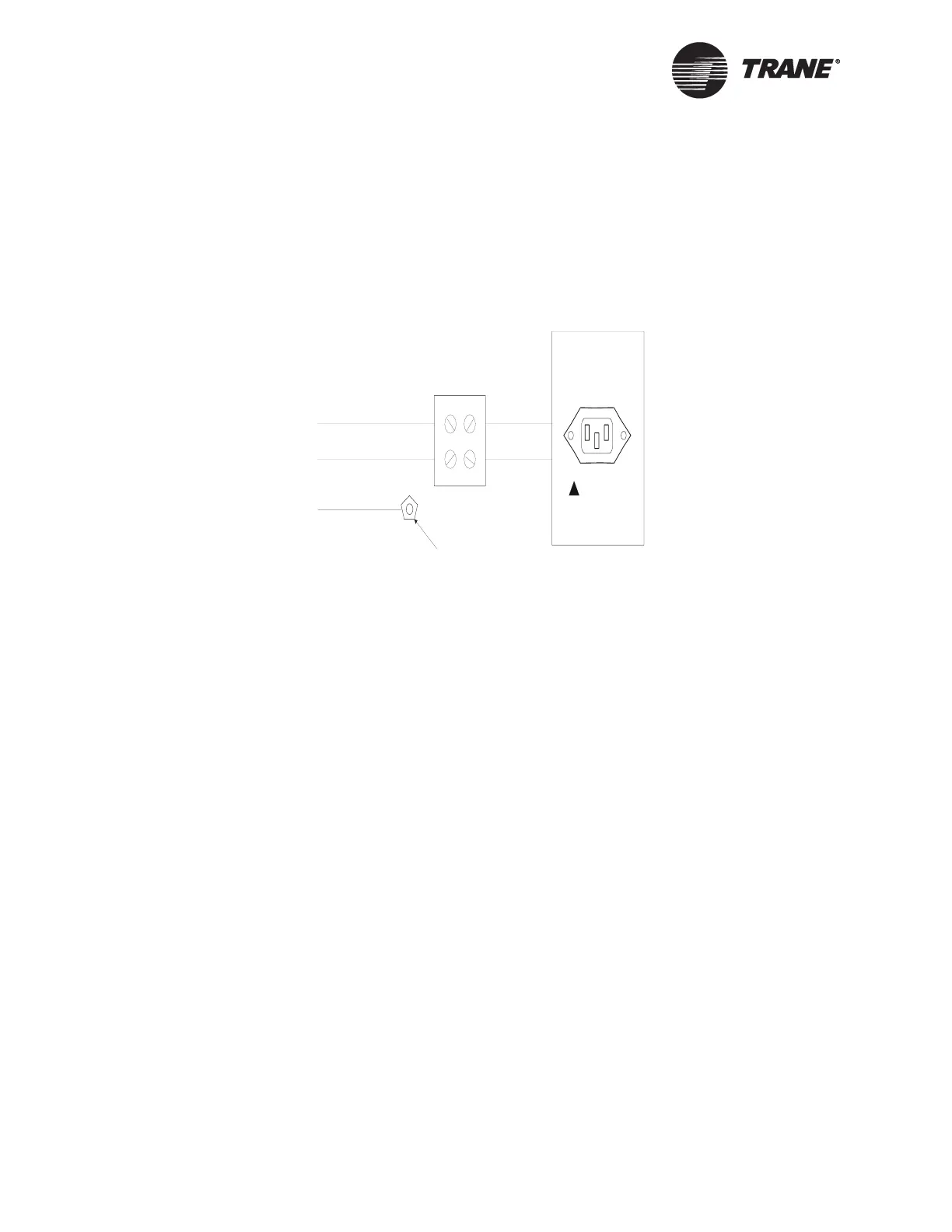
Figure 7. Tracer Summit BCU Power Supply Wiring
BCU Mounting and Power Wiring for
International Installations
The BCU mounting procedure consists of selecting a location, verifying
conformance to BCU and clearance specifications, and securing the BCU
to a wall. The BCU wiring procedure consists of verifying compliance with
the BCU circuit requirements and then connecting the ac-power wires.
BCU Mounting for International Installations
To mount a BCU:
1. Select a location.
2. Verify that the location conforms to BCU specifications.
3. Verify that the location conforms to clearance specifications for the
BCU.
4. Secure the BCU to the wall.
5. Install the optional operator display.
Select a Location
Select a location for the BCU that is in a corrosion-free, clean, indoor
environment. Consider both security and control wire lengths when mak-
ing the selection. The location should limit access to the BCU to operating
and service personnel.
230 Vac (blue)
Ground (green)
230 Vac (brown)
SERVICE TOOL ONLY
4 AMP MAX
Ground lu
!

 Loading...


