BCU Mounting and Power Wiring for European Community Installations
BMTW-SVN01F-EN 21
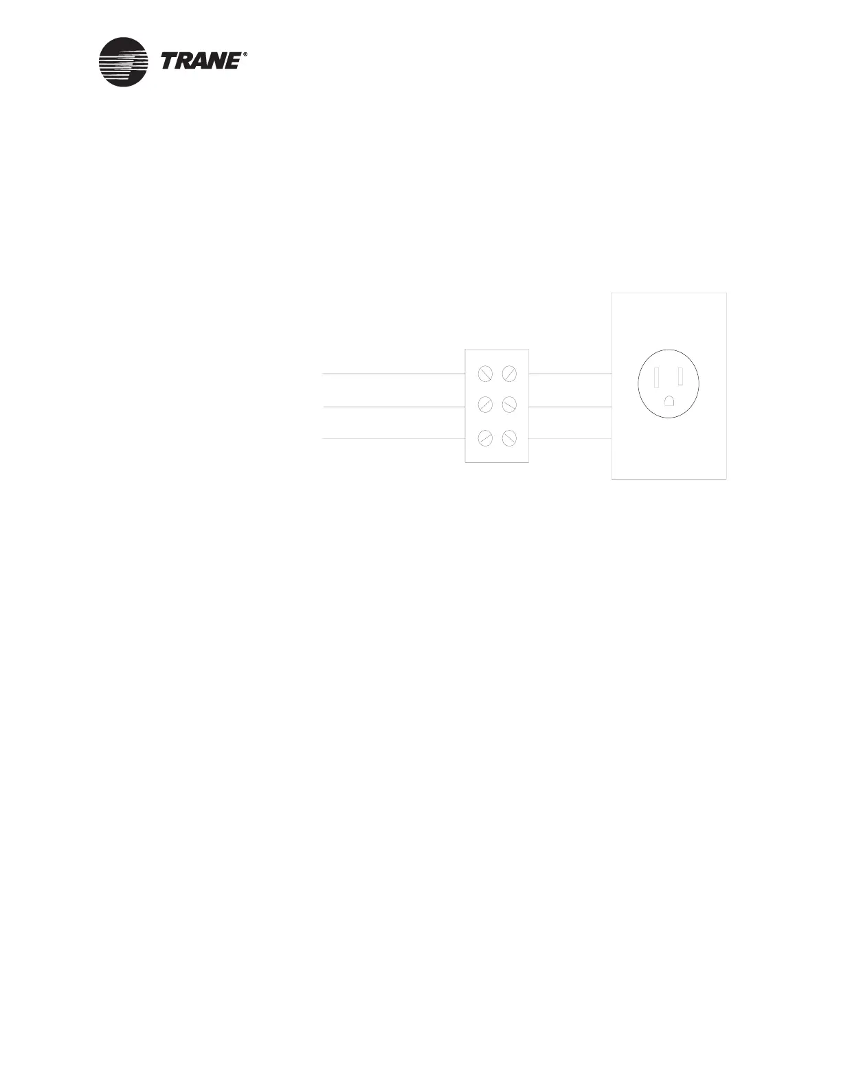
CAUTION
4-Amp maximum set up tool receptacle
The SET UP TOOL ONLY receptacle must be used only to power a lap-
top PC service tool. The PC must not exceed a 4 A draw with a maxi-
mum acceptable leakage current of 3.4 mA.
Figure 6. Tracer Summit BCU Power Supply Wiring
BCU Mounting and Power Wiring for
European Community Installations
The BCU mounting procedure consists of selecting a location, verifying
conformance to BCU and clearance specifications, and securing the BCU
to a wall. The BCU wiring procedure consists of verifying compliance with
the BCU circuit requirements and then connecting the ac-power wires.
nCAUTION
Avoid Personal Injury!
Install the BCU only in the manner specified by Trane. Failure to do so
may result in personal injury and/or damage to equipment.
BCU Mounting for European Community Installations
To mount a BCU:
1. Select a location.
2. Verify that the location conforms to BCU specifications.
3. Verify that the location conforms to clearance specifications for the
BCU.
4. Secure the BCU to the wall.
5. Install the optional operator display.
120 Vac hot (black)
120 Vac neutral (white)
Ground (green)
SET UP TOOL ONLY
4 AMP MAX

 Loading...


