Centrifugal/Absorption/Helical Rotary Chiller (UCP2) Interface
BMTW-SVN01F-EN 73
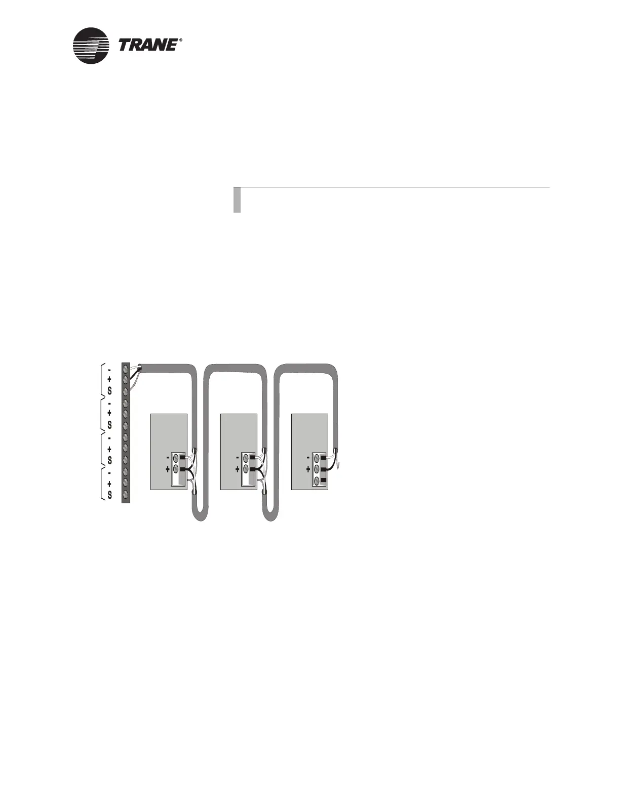
To connect the shield:
◆ Connect the shield at the BCU (TB2) to provide a drain for RFI/EMI,
and then splice it with other UCP2 chiller shields at the UCP2 chiller
end. Tape the shield at the last UCP2 chiller in the chain to prevent
any connection between the shield and ground (see Figure 35).
IMPORTANT
UCM ground loops will cause a malfunction.
From the UCP2 operator settings menu on the front panel, change the
setpoint source override item to NONE to allow Tracer Summit control. If
this setting is not changed, Tracer Summit is only able to monitor the
UCP2.
Figure 35. ICS Connections Between the BCU and UCP2s on a Comm4
Link
Device Addressing
Each UCM must have a unique address on each link. On the UCP2,
addresses are set from the front panel. Refer to the UCP2 installation,
operation, and maintenance manual for details.
Note:
Observe the polarity throughout communication links.
Device #3
Comm Link
Terminal Block
Device #1
Cut and tape
the shield
wires together.
Device #2
Cut and tape
the shield
wires together.
Cut and tape
back the
shield wire.
1
2
3
4
5
6
7
8
9
10
11
12
Link 1
Link 2
Link 3
Last device on
the Comm4 link
Shield Shield Shield
Comm Link
Terminal Block
Comm Link
Terminal Block
Link 4

 Loading...


