Chapter 5 UCM Wiring and Addressing
98 BMTW-SVN01F-EN
To connect shield:
1. Connect the shield at the BCU (TB2) to provide a drain for RFI/EMI,
and then splice it with other RTA/RTW shields at the RTA/RTW end.
2. Tape the shield at the last RTA/RTW in the chain to prevent any con-
nection between the shield and ground (see Figure 46).
IMPORTANT
UCM ground loops will cause a malfunction.
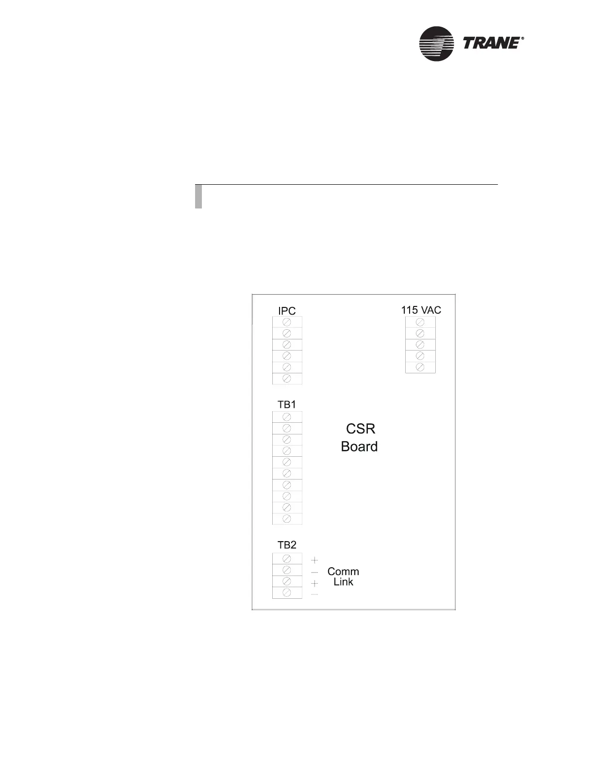
Figure 46. Location of UCM Communication-link Terminations on the
CSR Board on the RTA-RTW UCM
Device Addressing
Each UCM must have a unique address on each link. On the RTA/RTW,
addresses are set from the front panel. Refer to the RTA/RTW installa-
tion, operation, and maintenance manual for details.
Note:
Observe the polarity throughout communication links.

 Loading...


