Horizon Absorption Chiller Interface
BMTW-SVN01F-EN 81
stector protectors through Trane. Contact your local Trane sales office for
details.
In a daisy chain configuration, use one pair of wires that start at the BCU
and go to all UCMs in a continuous loop. A branch configuration is possi-
ble if you need to tap into a daisy chain. Limit the total aggregate length
of the wiring for each communication link to 5,000 ft (1,524 m).
To connect communication wiring:
◆ Attach one end of the communication-link wiring to TB2 on the BCU.
For the location of TB2, refer to Figure 16 on page 47. The communi-
cation-link wiring must be connected to the TCI4-Comm4 module on
the communication-link terminal block (J3-A or J3-B)
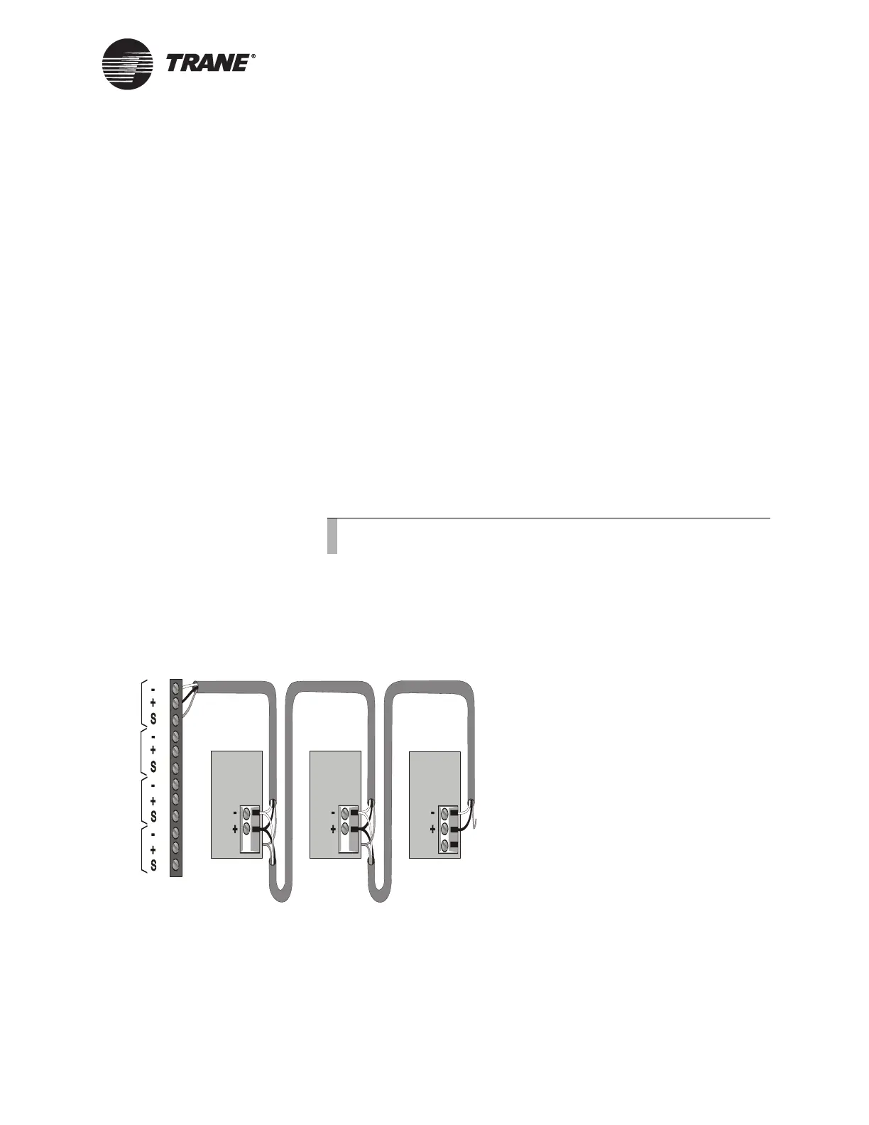
To connect the shield:
Connect the shield at the BCU (TB2) to provide a drain for RFI/EMI, and
then splice it with other Horizon shields at the Horizon end. Tape the
shield at the last Horizon in the chain to prevent any connection between
the shield and ground (refer to Figure 39). If polarity is reversed and the
BCU is both configured and connected, the green RX light on the TCI4-
Comm4 board will be ON solid.
IMPORTANT
UCM ground loops will cause a malfunction.
Figure 39. ICS Connections Between the BCU and Horizon Interface on
a Comm4 Link
Device Addressing
Each UCM must have a unique address on each link. On the Horizon
chiller, addresses are set from the front panel. Refer to the Horizon chiller
installation, operation, and maintenance manual for details.
Note:
Observe the polarity throughout communication links.
Device #3
Comm Link
Terminal Block
Device #1
Cut and tape
the shield
wires together.
Device #2
Cut and tape
the shield
wires together.
Cut and tape
back the
shield wire.
1
2
3
4
5
6
7
8
9
10
11
12
Link 1
Link 2
Link 3
Last device on
the Comm4 link
Shield Shield Shield
Comm Link
Terminal Block
Comm Link
Terminal Block
Link 4

 Loading...


