Chapter 2 BCU Mounting and Power Wiring
32 BMTW-SVN01F-EN
3. Check card locations to assure they are in the communication module
slot(s) corresponding to UCM communication link wiring on TB1.
4. Locate the four snap-clip receptors on the BCU metal back panel and
align with the four snap clips on the BCU logic board assembly.
5. Firmly press the two upper snap clips, then the two lower snap clips,
on to the receptors. Make sure the BCU logic board assembly is fully
secured to the BCU back panel.
6. With the ac power off, connect the plug from the power transformer to
TB1 on the upper right corner of the BCU board card.
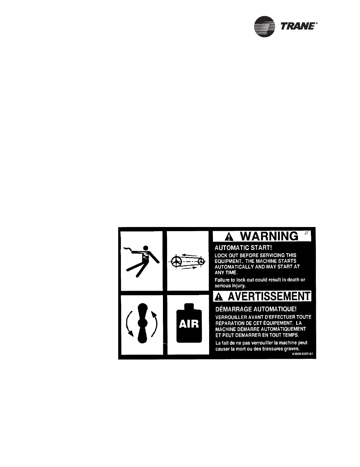
BCU Warning Labels
A supply of warning labels (form number X39001257-01) is shipped with
each BCU (see Figure 9). Use these labels to warn operating, mainte-
nance, and service personnel about the potential hazards associated with
automatically controlled equipment.
Before making any control wiring connections, place one or more labels in
conspicuous locations on each piece of controlled equipment.
Figure 9. BCU warning label
Installing and Removing the BCU Cover
The BCU has a resin cover that protects the internal components from
damage. The cover slips easily onto the BCU metal back panel and locks
for security purposes.

 Loading...


