Chapter 4 UCM Communication-Link Wiring
60 BMTW-SVN01F-EN
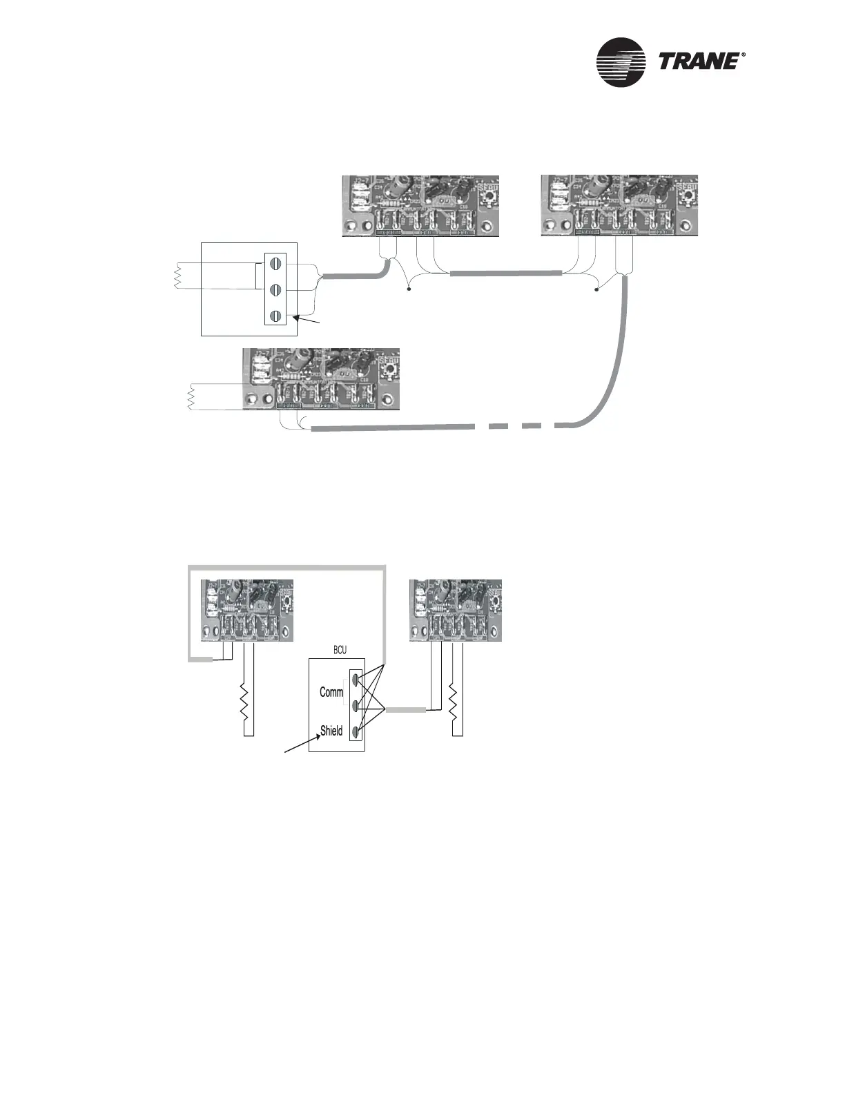
Figure 27. Daisy Chain Resistor Placement
Figure Note:
A continuous shield is required when shielded wire is used. At each controller,
splice shield wire and tape back to prevent grounding. Connect shield wire to
earth ground at the BCU and repeater. If unshielded communication wire is
used, no shield connections are necessary.
Figure 28. Alternate Daisy Chain Resistor Placement
Comm5 Physical Link Repeater
The Comm5 link repeater is a device that repeats and regenerates the
signal on a Comm5 link. The Comm5 link goes from the BCU to the
repeater and a second link segment extends from the other side of the
repeater to the rest of the devices. The configurations on either side of the
repeater should be daisy chain. Both link segments require proper
termination.
BCU
Comm
Shield
105
Termination
resistor
Ω
105
Termination
resistor
Ω
Splice
Splice
Shield connection not used
for unshielded wire
com
105
Termination
Resistor
Ω
105
Termination
Resistor
Ω
Shielded connection not used
for unshielded wire

 Loading...


