EasyManuals Logo

Trane Tracer MP581/AH541 User Manual

Trane Tracer MP581/AH541
272 pages
To Next Page IconTo Next Page
To Previous Page IconTo Previous Page
Page #110 background imageLoading...
Page #110 background image
Programmable Control Module (PCM) Interface
BMTW-SVN01F-EN 95
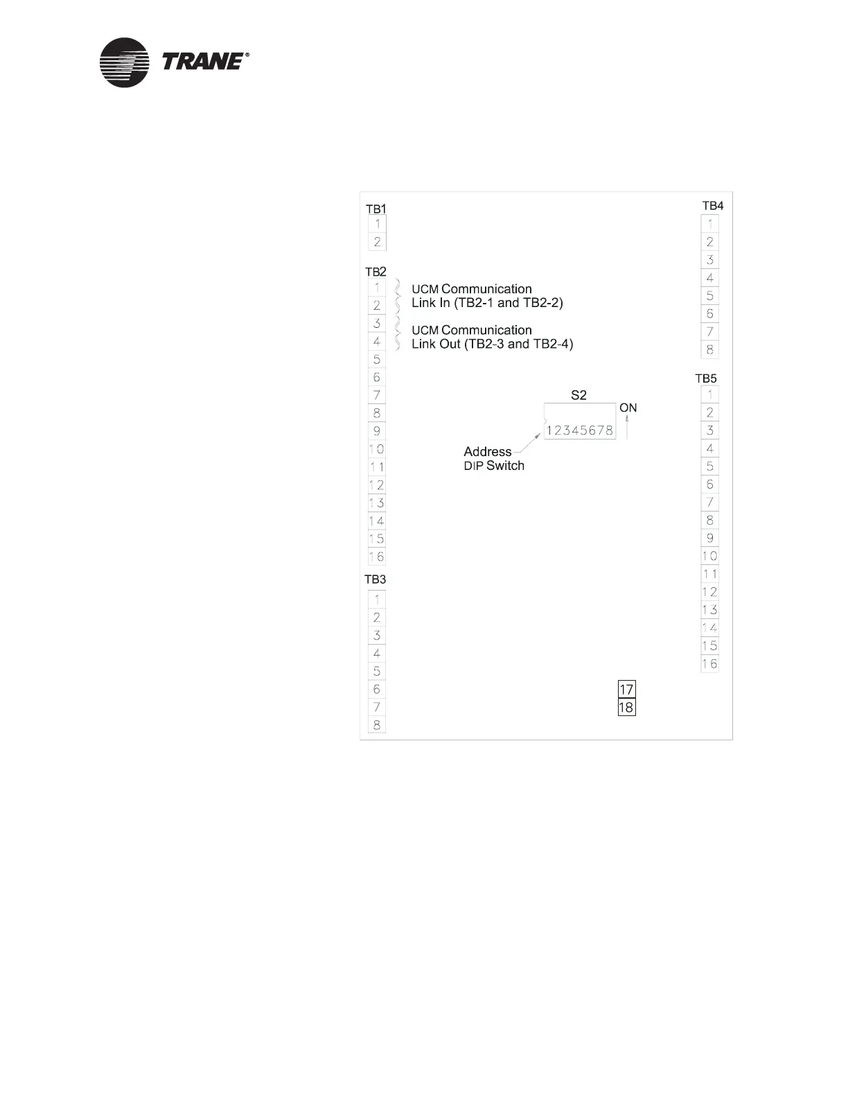
Figure 45. Location of Address DIP Switches and UCM Communication
Link on the PCM
Figure Note:
PCM board is much wider than shown here.
Device Addressing
Each UCM must have a unique address on each link. On the PCM, the
address is set with the S2 address DIP switches (see Figure 45). For PCM
DIP switch settings, refer to Table 16 on page 96.

Table of Contents

Other manuals for Trane Tracer MP581/AH541

Questions and Answers:

Question and Answer IconNeed help?

Do you have a question about the Trane Tracer MP581/AH541 and is the answer not in the manual?

Trane Tracer MP581/AH541 Specifications

General IconGeneral
BrandTrane
ModelTracer MP581/AH541
CategoryControl Systems
LanguageEnglish

Related product manuals