Installing and Wiring the BCU Logic Board
BMTW-SVN01F-EN 31
2. Make sure that all internal connections are secure, then check for ac
or dc voltages for safety purposes. For BCU input power wiring and
internal cable connections, see Figure 2 on page 4.
3. Check for ac and dc shorts to ground by disconnecting all power to the
BCU and measuring the resistance between the hot and neutral leads
on the 120/240 Vac power supply. The proper resistance reading
should be 33 Ω (5 Ω with an optional 24 Vac transformer).
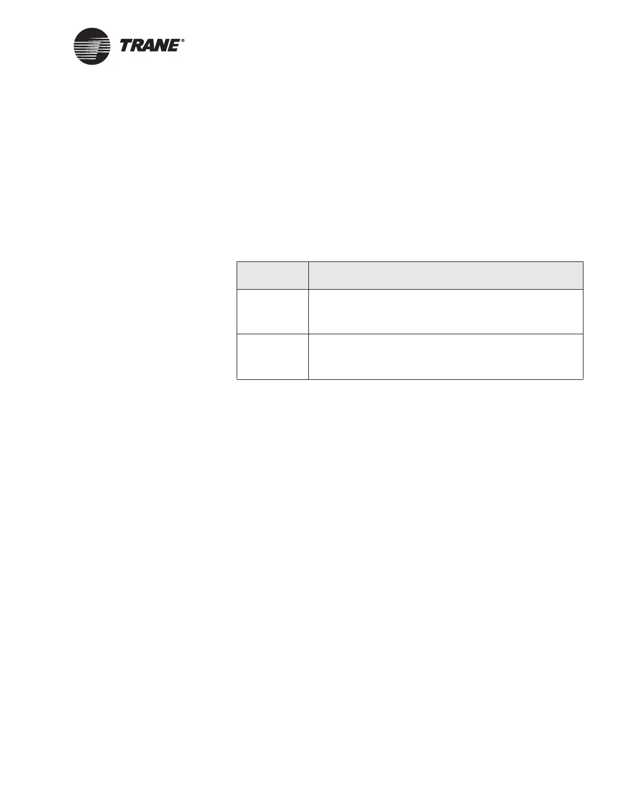
4. Energize the BCU power supply circuit, and then check the voltage
between each pair of wires on the ac-power termination block. The
voltages measured should match the values in Table 4.
5. De-energize the BCU power supply circuit by opening the circuit
breaker at the power distribution circuit breaker panel.
6. Reinstall the block-off cover over the power supply area in the BCU
enclosure.
Installing and Wiring the BCU Logic
Board
The BCU logic board assembly is shipped in its own packaging so that it
can be stored in a safe location while construction or electrical wiring is in
progress. After all ac-power wiring is complete, mount and wire the BCU
logic board assembly.
CAUTION
Possible Equipment Damage!
The BCU logic board should be installed only after building construc-
tion or electrical wiring is at a point when there is no risk of damaging
the electronics of the logic board.
To install and wire the logic board:
1. Remove the BCU logic board assembly from the packaging material.
2. Inspect the applicable unit control module (UCM) communication
card(s) to make sure that the communication options are as ordered.
Table 4. BCU Power Supply Voltages
Power Voltages
120 Vac
• 98–132 Vac between black wire and white wire
• Less than 5 Vac between white wire and ground
• 98–132 Vac between black wire and ground
240 Vac
• 196–264 Vac between black wire and orange wire
• 98–132 Vac between orange wire and ground
• 98–132 Vac between black wire and ground

 Loading...


