Terminal Unit Controller (TUC) Interface
BMTW-SVN01F-EN 105
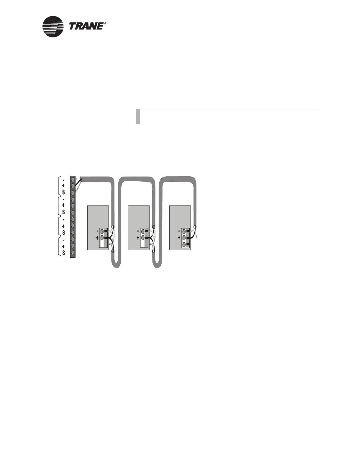
To connect shield:
Connect the shield at the BCU (TB2) to provide a drain for RFI/EMI, and
then splice it with other TUC shields at the TUC end. Tape the shield at
the last TUC in the chain to prevent any connection between the shield
and ground (see Figure 50).
IMPORTANT
UCM ground loops will cause a malfunction.
Figure 50. ICS Connections Between the BCU and TUCs on a Comm4
Link
Device Addressing
Each UCM must have a unique address on each link. On the TUC, the
address is set with the SW1 address DIP switches, followed by a momen-
tary short between J11 and J12 (see Figure 51 on page 106). For TUC
DIP switch settings, refer to Table 18 on page 107.
Note:
Observe the polarity throughout communication links.
Device #3
Comm Link
Terminal Block
Device #1
Cut and tape
the shield
wires together.
Device #2
Cut and tape
the shield
wires together.
Cut and tape
back the
shield wire.
1
2
3
4
5
6
7
8
9
10
11
12
Link 1
Link 2
Link 3
Last device on
the Comm4 link
Shield Shield Shield
Comm Link
Terminal Block
Comm Link
Terminal Block
Link 4

 Loading...


