Chapter 5 UCM Wiring and Addressing
118 BMTW-SVN01F-EN
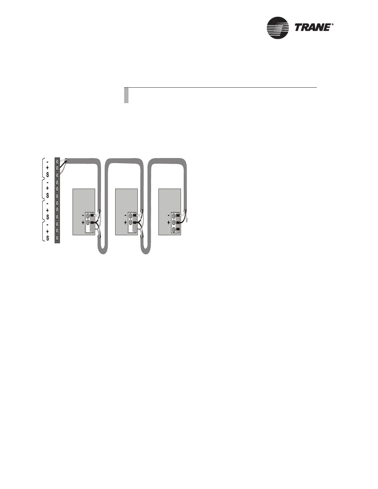
at the last UPCM in the chain to prevent any connection between the
shield and ground (see Figure 55).
IMPORTANT
UCM ground loops will cause a malfunction.
Figure 55. ICS Connections Between the BCU and UPCMs on a Comm4
Link
Device Addressing
Each UCM must have a unique address on each link. On the UPCM, the
address is set with the SW1 address DIP switches (see Figure 56 on
page 119).
For UPCM DIP switch settings, refer to Table 22 on page 119. DIP switch
settings for BCU addresses 32 through 41 are shown in this table, but you
can place UPCMs anywhere from address 32 to 100.
Note:
Observe the polarity throughout communication links.
Device #3
Comm Link
Terminal Block
Device #1
Cut and tape
the shield
wires together.
Device #2
Cut and tape
the shield
wires together.
Cut and tape
back the
shield wire.
1
2
3
4
5
6
7
8
9
10
11
12
Link 1
Link 2
Link 3
Last device on
the Comm4 link
Shield Shield Shield
Comm Link
Terminal Block
Comm Link
Terminal Block
Link 4

 Loading...


