VAV Wireless Receiver Interface
BMTW-SVN01F-EN 135
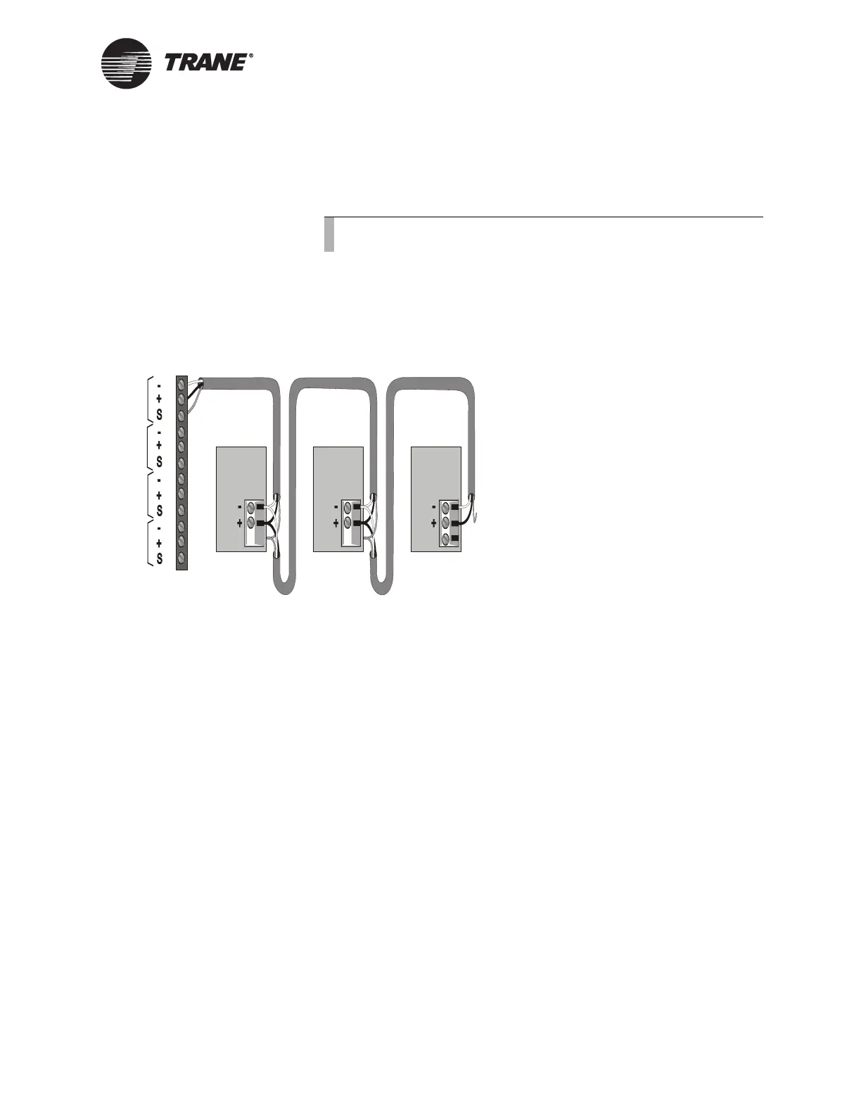
2. Tape the shield at the last VAV wireless receiver in the chain to pre-
vent any connection between the shield and ground (see Figure 62 on
page 135).
IMPORTANT
UCM ground loops will cause a malfunction.
Figure 62. ICS Connections Between the BCU and VAV Wireless
Receivers on a Comm4 Link
Device Addressing
Each UCM must have a unique address on each link. wireless receivers
can have an address from 1 through 31. The address is set with the DIP
switches located on the side of the wireless receiver (see Figure 61 on
page 134). For VAV wireless receiver DIP switch settings, refer to
Table 26 on page 136.
Note:
Observe the polarity throughout communication links.
Device #3
Comm Link
Terminal Block
Device #1
Cut and tape
the shield
wires together.
Device #2
Cut and tape
the shield
wires together.
Cut and tape
back the
shield wire.
1
2
3
4
5
6
7
8
9
10
11
12
Link 1
Link 2
Link 3
Last device on
the Comm4 link
Shield Shield Shield
Comm Link
Terminal Block
Comm Link
Terminal Block
Link 4

 Loading...


