Chapter 2 BCU Mounting and Power Wiring
36 BMTW-SVN01F-EN
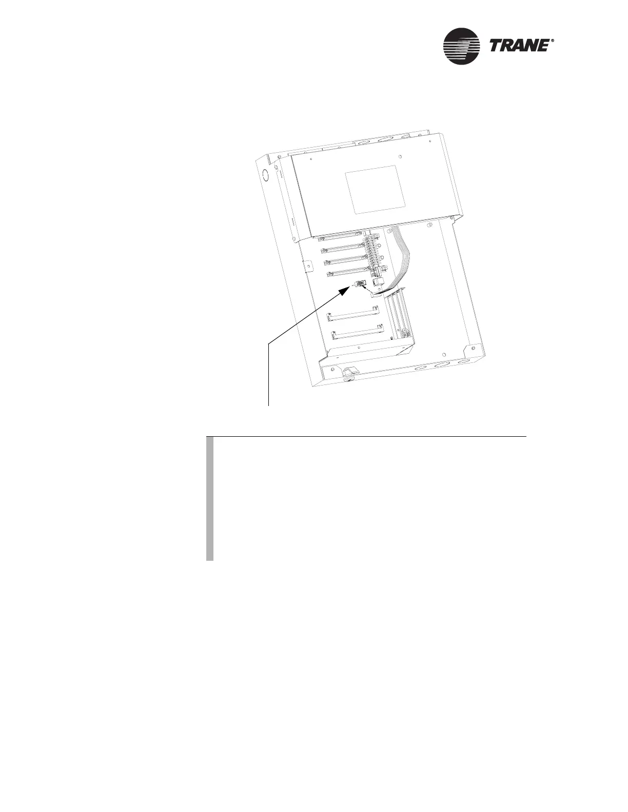
Figure 12. Operator display socket
IMPORTANT
The operator display will not function properly if the mini-monitor is
plugged into P6 on the BCU logic board. (The mini-monitor is software
and cabling that allows you to view BCU information on an attached
PC.) If you need to attach the mini-monitor cable, first unplug the oper-
ator display from the P13 operator display socket on the BCU logic
board.
Operator display socket
Note:
The operator display emits a beep every 10 minutes if the oper-
ator display is powered up and either the BCU is not configured
or communication has been lost between the BCU and the oper-
ator display. Therefore, if you are installing the operator dis-
play on a BCU that has not been configured, the operator
display will beep. You may want to wait to power up the opera-
tor display until the BCU has been configured. To do so, simply
keep the ribbon cable disconnected from the P13 operator dis-
play socket on the BCU logic board.

 Loading...


