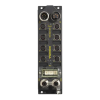
Application example FGEN for Modbus TCP with CODESYS Win V3
D301271 1013 - FGEN - multi protocol10-22
4 Write:
Parameters of the station FGEN-XSG16-5001
target → inverting the input signal at channel 5
Writing parameters is normally done once during the program start and is thus not set as a "normal"
Modbus channel under "ModbusSlave Channel", but as an Initialization channel under "Modbus
Slave Init" (see Figure 10-21: Setting the initialization channel for the parameterization).
– Access Type:
Write Single Register (function code 06)
– Write Register, Offset:
0×B001 (see Register mapping of the FGEN-stations, FGEN-XSG16-x001 (page 9-14))
The parameters of the station can be found in register 0xB000 to 0×B003.
Parameterization of the station
The parameterization to be done here is to invert the input signal at channel 5 (I.5) of the station
(register 0×B001, bit 5).
The parameter register is build up as follows:
A 2
5
= 32 will be written to register 0×B001, which results from the station's the parameter byte
assignment.
Reg. Bit 7 Bit 6 Bit 5 Bit 4 Bit 3 Bit 2 Bit 1 Bit 0
0×B000--------
--------
0×B001 Inv. DI7 Inv. DI6 Inv. DI5 Inv. DI4 Inv. DI3 Inv. DI2 Inv. DI1 Inv. DI0
Inv. DI15 Inv. DI14 Inv. DI13 Inv. DI12 Inv. DI11 Inv. DI10 Inv. DI9 Inv. DI8
0×B002 SRO7 SRO6 SRO5 SRO4 SRO3 SRO2 SRO1 SRO0
SRO15 SRO14 SRO13 SRO12 SRO11 SRO10 SRO9 SRO8
0×B003-------
-------
Figure 10-21:
Setting the ini-
tialization chan-
nel for the
parameteriza-
tion

 Loading...