4 Power Cable Connections
4.1 Main System Input Connection
CAUTION: Before wiring, ensure the mainMCB is open and disconnected.
To connect the main cabinet system power cables:
1. Cut the appropriate length according to the specifications detailed in the table.
Input
Power
Capacity
Minimum Cable Cross-
Sectional Area (AWG)
(Ambient Temperature: 25
°C/77 °F)
Open Space
Minimum
Size
Yellow-Green Ground Wire
Cross-Sectional Area (mm2)
(Ambient Temperature: 25
°C/77 °F)
Into the server room to
the distribution line
products and open space
10 kVA 3 3P 100A 16
20 kVA 2/0 3P 175A 35
Table 4.1 Cable Specifications
2. Based on the wire diameter of the cable, select the appropriate M6 terminal and crimp the cable.
NOTE: When passing the cable through the top rubber hole, ensure the rubber is installed correctly.
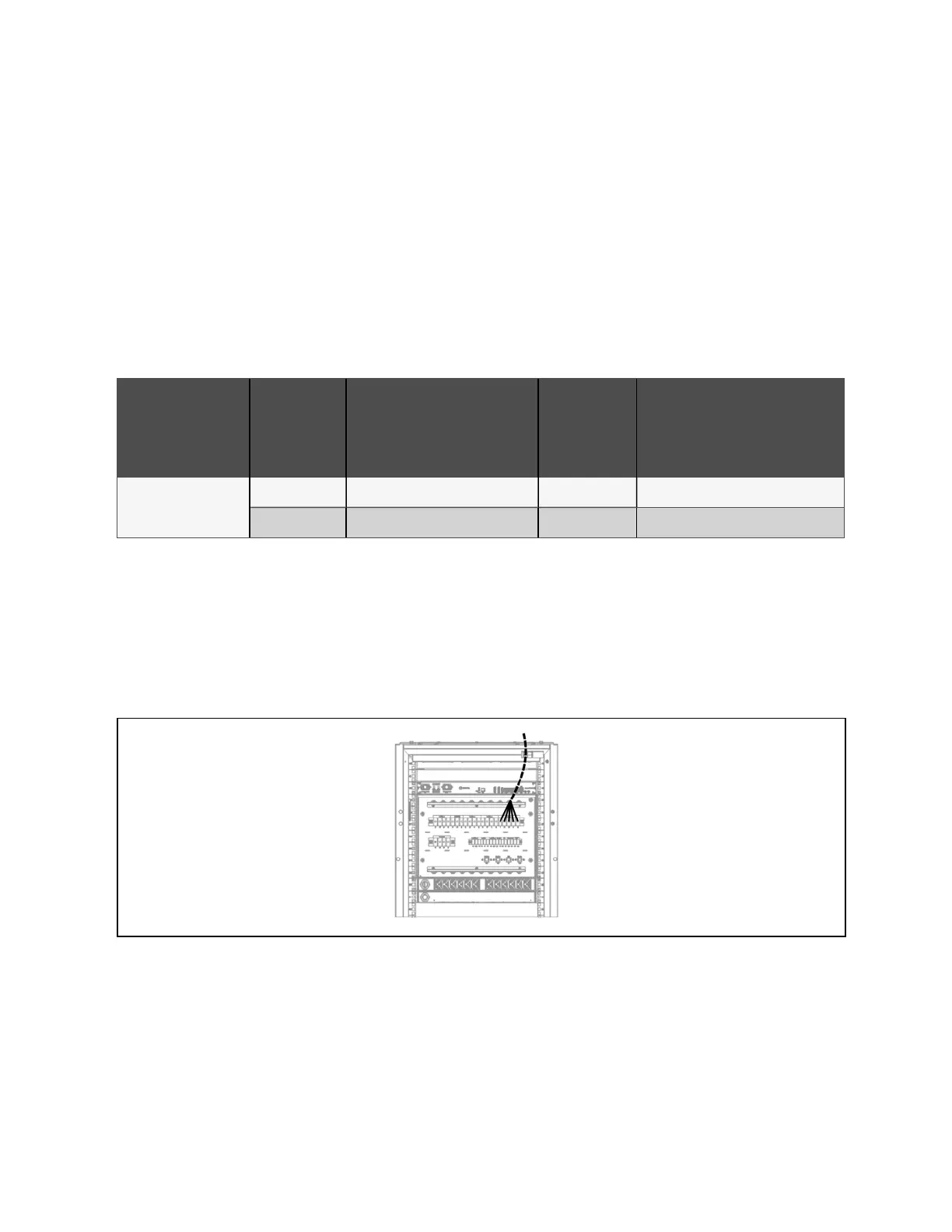
3. Pass the cut cable through the right side of the PMC , as shown in PMC10/20 System Input Power Cabling Route
below .
4. Follow the silk screen to the AC input terminal block and PMC (10kVA/20kVA UPS).
Figure 4.1 PMC10/20 System Input Power Cabling Route
5. After the wiring is completed, use the cable tie to fix the input cable to the side of the cable management board
for strain relief.
6. Connect the system input ground to the main grounding bar. Please select the appropriate wire diameter
according to Cable Specifications above .
4 Power Cable Connections Proprietary and Confidential ©2024 Vertiv Group Corp. 31
Vertiv™ SmartRow™ 2 Infrastructure Solution User Guide